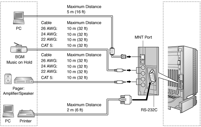
3.12 Connection of Peripherals
3.12.1 Connection of Peripherals
PC (via MNT Port)
| A PC can be connected to the PBX via the MNT port of the IPCMPR card. It is used for system programming, diagnostics and external system database storage (save/load) functions. |
|
Pin Assignments
|
| |
No. |
Signal Name |
Input (I)/Output (O) |
Function | |
|
|
|
|
| |
|
|
|
| |
|
|
|
| |
|
|
|
| |
|
|
|
| |
|
|
|
|
|
BGM/MOH
| The PBX provides Background Music and Music on Hold. Up to 2 external music sources (e.g., user-supplied radios) can be connected to the PBX. |
CAUTION
|
• |
Wiring should be done carefully to prevent undue force being exerted on the plug. Otherwise, sound may only be heard intermittently. |
|
• |
External Music Jacks are SELV ports and should only be connected to approved SELV devices. |
|
Note
|
When the PBX and external music sources are not connected to the same ground, hum noise may be induced into Background Music and Music on Hold. |
|
Pager
| Up to 2 paging devices (user-supplied) can be connected to the PBX. |
CAUTION
|
External Paging Jacks are SELV ports and should only be connected to approved SELV devices. |
|
PC/Printer (via RS-232C)
The PBX is equipped with an RS-232C interface. This interface provides communication between the PBX and the user-supplied devices such as PC or line printers. The RS-232C port is used for system programming, SMDR, diagnostics and external system database storage (save/load) functions.
When using special accessories such as cable, the user should use those specified in this installation manual to comply with the limits for a Class B digital device pursuant to the FCC Rules. |
IMPORTANT
|
To protect the system, keep the following in mind: |
| 1. |
Make sure that both connector cases (frame ground) of the RS-232C cross cable (shielded cable) are conductive. If they are not conductive, make sure that both connector cases of the cable are firmly connected. |
| 2. |
If this is not possible, connect the frame of the PBX to the frame of the PC/Printer using an earthing wire in order to prevent difference in the electrical potentials. |
|
|
Pin Assignments
|
| |
No. |
Signal Name |
Function |
Circuit Type | |
EIA |
CCITT | |
|
|
|
|
|
| |
|
|
| Transmit Data |
| Data Terminal Ready |
|
|
| |
|
|
| Signal Ground |
| Data Set Ready |
|
|
| |
|
|
| Request To Send |
| Clear To Send |
|
|
|
|
|
Connection Charts
|
| For connecting a printer/PC with a 9-pin RS-232C connector |
|
|
| For connecting a printer/PC with a 25-pin RS-232C connector |
|
|
| RS-232C Signals |
| • |
Receive Data (RXD):…(input)
Conveys signals from the printer or the PC. |
| • |
Transmit Data (TXD):…(output)
Conveys signals from the unit to the printer or the PC. A "Mark" condition is held unless data or BREAK signals are being transmitted. |
| • |
Data Terminal Ready (DTR):…(output)
This signal line is turned ON by the unit to indicate that it is ON LINE. Circuit ER (DTR) ON does not indicate that communication has been established with the printer or the PC. It is switched OFF when the unit is OFF LINE. |
| • |
Signal Ground (SG)
Connects to the DC ground of the unit for all interface signals. |
| • |
Data Set Ready (DSR):…(input)
An ON condition of circuit DR (DSR) indicates the printer or the PC is ready. Circuit DR (DSR) ON does not indicate that communication has been established with the printer or the PC. |
| • |
Request To Send (RTS):…(output)
This lead is held ON whenever DR (DSR) is ON. |
| • |
Clear To Send (CTS):…(input)
An ON condition of circuit CS (CTS) indicates that the printer or the PC is ready to receive data from the unit. The unit does not attempt to transfer data or receive data when circuit CS (CTS) is OFF. |
| • |
Frame Ground (FG)
Connects to the unit frame and the ground conductor of the AC power cord. |
|

