3.5 Information about the Physical CO Line Cards
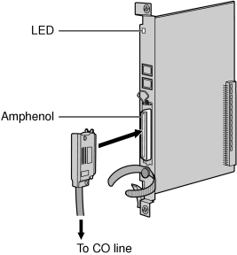
3.5.1 LCOT8 Card (KX-TDA0180) and LCOT16 Card (KX-TDA0181)
Function
|
Accessories and User-supplied Items
|
| Accessories (included): Screws × 2 |
| User-supplied (not included): Amphenol connector |
Pin Assignments
|
Amphenol Connector
|
| |
No. |
Signal Name |
Function |
No. |
Signal Name |
Function | |
|
|
|
|
|
|
| |
|
|
|
|
|
| |
|
|
|
|
|
| |
|
|
|
|
|
| |
|
|
|
|
|
| |
|
|
|
|
|
| |
|
|
|
|
|
| |
|
|
|
|
|
| |
|
|
|
|
|
| |
|
|
|
|
|
| |
|
|
|
|
|
| |
|
|
|
|
|
| |
|
|
|
|
|
| |
|
|
|
|
|
| |
|
|
|
|
|
| |
|
|
|
|
|
| |
|
|
|
|
|
|
|
Notes
|
• |
Pin assignments for the pins 5 to 8 and 30 to 33 are for the LCOT8 and LCOT16 card only. |
|
• |
Pin assignments for the pins 9 to 16 and 34 to 41 are for the LCOT16 card only. |
|
LED Indications
|
Indication |
Color |
Description |
|
|
|
| • |
OFF: Power Off |
| • |
Green ON: Normal (all ports are idle) |
| • |
Green Flashing (60 times per minute): Normal (a port is in use) |
| • |
Red ON: Fault (includes reset) |
| • |
Red Flashing (60 times per minute): Out of Service |
|
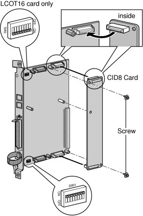
3.5.2 CID8 Card (KX-TDA0193)
Function
|
Accessories and User-supplied Items
|
| Accessories (included): Screws × 2 |
| User-supplied (not included): none |
Note
|
Only 1 CID8 card can be mounted on the LCOT8 card. |
Switch Settings (on LCOT8/LCOT16 cards)
|
Switch |
Type |
Usage and Status Definition |
|
|
|
| Keep all DIP switches at default "ON" positions. Do not change the positions of these switches. |
Note
|
SW2 is for the LCOT16 card only. |
|
|
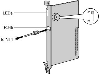
3.5.3 T1 Card (KX-TDA0187)
Function
|
Accessories and User-supplied Items
|
| Accessories (included): none |
| User-supplied (not included): RJ45 connector |
Notes
|
• |
Connect this optional service card to the CO line through NT1; do not connect to the CO line directly. |
|
• |
T1 Card must be installed behind an FCC registered and UL or CSA-NRTL listed CSU. |
|
• |
To confirm the CO line connection, refer to "Confirming the CO Line Connection" in "3.15.1 Starting the PBX". |
CAUTION
|
T1 ports are SELV ports and should only be connected to SELV services. |
Switch Settings
|
Switch |
Type |
Usage and Status Definition |
|
|
|
| Keep the switch at default A position. Do not change the position of this switch. |
|
Pin Assignments
|
RJ45 Connector
|
| |
No. |
Signal Name |
Level [V] |
Function | |
|
|
|
|
| |
|
|
|
| |
|
|
|
| |
|
|
|
| |
|
|
|
| |
|
|
|
|
|
LED Indications
|
Indication |
Color |
Description |
|
|
|
| • |
OFF: Power Off |
| • |
Green ON: Normal (all ports are idle) |
| • |
Green Flashing (60 times per minute): Normal (a port is in use) |
| • |
Red ON: Fault (includes reset) |
| • |
Red Flashing (60 times per minute): Out of Service |
|
|
|
|
| Non-synchronization status indication |
| • |
OFF: Normal |
| • |
ON: Out of synchronization |
|
|
|
|
| RAI signal status indication |
| • |
OFF: Normal |
| • |
ON: Alarm (Clock Slave) |
| • |
Flashing (60 times per minute): Alarm (Clock Master) |
|
|
|
|
| • |
OFF: Normal |
| • |
ON: Alarm |
|
|
|
|
| Synchronization status indication |
| • |
OFF: Not synchronized |
| • |
ON: Synchronized |
| • |
Flashing (60 times per minute): Synchronized (Clock Master) |
|
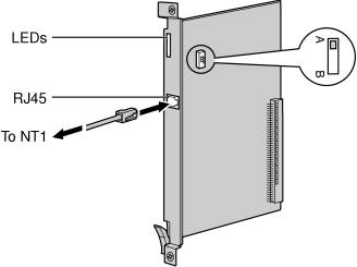
3.5.4 PRI23 Card (KX-TDA0290)
Function
|
Accessories and User-supplied Items
|
| Accessories (included): none |
| User-supplied (not included): RJ45 connector |
CAUTION
|
PRI ports are SELV ports and should only be connected to SELV services. |
Switch Settings
|
Switch |
Type |
Usage and Status Definition |
|
|
|
| Keep the switch at default A position. Do not change the position of this switch. |
|
Pin Assignments
|
RJ45 Connector
|
| |
No. |
Signal Name |
Level [V] |
Function | |
|
|
|
|
| |
|
|
|
| |
|
|
|
| |
|
|
|
| |
|
|
|
| |
|
|
|
|
|
LED Indications
|
Indication |
Color |
Description |
|
|
|
| • |
OFF: Power Off |
| • |
Green ON: Normal (all ports are idle) |
| • |
Green Flashing (60 times per minute): Normal (a port is in use) |
| • |
Red ON: Fault (includes reset) |
| • |
Red Flashing (60 times per minute): Out of Service |
|
|
|
|
| Non-synchronization status indication |
| • |
OFF: Normal |
| • |
ON: Out of synchronization |
|
|
|
|
| RAI signal status indication |
| • |
OFF: Normal |
| • |
ON: Alarm (Clock Slave) |
| • |
Flashing (60 times per minute): Alarm (Clock Master) |
|
|
|
|
| • |
OFF: Normal |
| • |
ON: Alarm |
|
|
|
|
| Synchronization status indication |
| • |
OFF: Not synchronized |
| • |
ON: Synchronized |
| • |
Flashing (60 times per minute): Synchronized (Clock Master) |
|
|
|
|
| Data link status indication |
| • |
OFF: Not established |
| • |
ON: Established |
|
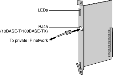
3.5.5 IP-GW4E Card (KX-TDA0484)
Function
|
Accessories and User-supplied Items
|
| Accessories (included): CD-ROM (including documentation for web programming) × 1 |
| User-supplied (not included): RJ45 connector |
Notes
|
• |
The maximum length of the cable to be connected to this optional service card is 100 m (328 ft). |
|
• |
The IP-GW4E card occupies the space of only 1 free slot when it is installed in the PBX. |
|
• |
For programming instructions and other information about the IP-GW4E card, refer to the documentation for the IP-GW4E card. To program the IP-GW4E card, use the web programming designed for the IP-GW4E card. |
|
• |
To confirm the CO line connection, refer to "Confirming the CO Line Connection" in "3.15.1 Starting the PBX". |
Pin Assignments
|
RJ45 Connector (10BASE-T/100BASE-TX)
|
| |
No. |
Signal Name |
Input (I)/Output (O) |
Function | |
|
|
|
|
| |
|
|
|
| |
|
|
|
| |
|
|
|
| |
|
|
|
| |
|
|
|
|
|
LED Indications
|
Indication |
Color |
Description |
|
|
|
| • |
OFF: Power Off |
| • |
Green ON: Normal (all ports are idle) |
| • |
Green Flashing (60 times per minute): Normal (a port is in use) |
| • |
Red ON: Fault (includes reset) |
| • |
Red Flashing (60 times per minute): Out of Service |
|
|
|
|
| On-line status indication |
| • |
ON: On-line mode |
| • |
OFF: Off-line mode |
| • |
Flashing: Maintenance mode |
Note
|
If the LINK indicator is OFF, the ONLINE indicator will also be OFF. |
|
|
|
|
| • |
OFF: Normal |
| • |
ON: Alarm |
|
|
|
|
| VoIP (H.323) process indication |
| • |
OFF: VoIP process inactive |
| • |
ON: VoIP process active |
|
|
|
|
| • |
OFF: Connection error |
| • |
ON: Normal connection |
|
|
|
|
| Data transmission indication |
| • |
OFF: No data transmitted |
| • |
ON: Data transmitting |
|
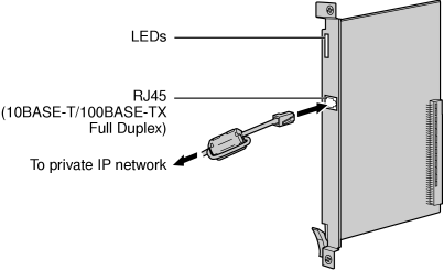
3.5.6 IP-GW16 Card (KX-TDA0490)
Function
|
Accessories and User-supplied Items
|
| Accessories (included): Ferrite core × 1, CD-ROM (including documentation for web programming) × 1 |
| User-supplied (not included): RJ45 connector |
Notes
|
• |
The maximum length of the cable to be connected to this optional service card is 100 m (328 ft). |
|
• |
When connecting the RJ45 connector, attach the included ferrite core. Refer to "3.2.8 Attaching a Ferrite Core". |
|
• |
For programming instructions and other information about the IP-GW16 card, refer to the documentation for the IP-GW16 card. To program the IP-GW16 card, use the web programming designed for the IP-GW16 card. |
|
• |
To confirm the CO line connection, refer to "Confirming the CO Line Connection" in "3.15.1 Starting the PBX". |
Pin Assignments
|
RJ45 Connector (10BASE-T/100BASE-TX)
|
| |
No. |
Signal Name |
Input (I)/Output (O) |
Function | |
|
|
|
|
| |
|
|
|
| |
|
|
|
| |
|
|
|
| |
|
|
|
| |
|
|
|
|
|
LED Indications
|
Indication |
Color |
Description |
|
|
|
| • |
OFF: Power Off |
| • |
Green ON: Normal (all ports are idle) |
| • |
Green Flashing (60 times per minute): Normal (a port is in use) |
| • |
Red ON: Fault (includes reset) |
| • |
Red Flashing (60 times per minute): Out of Service |
|
|
|
|
| On-line status indication |
| • |
ON: On-line mode |
| • |
OFF: Off-line mode |
| • |
Flashing: Maintenance mode |
Note
|
If the LINK indicator is OFF, the ONLINE indicator will also be OFF. |
|
|
|
|
| • |
OFF: Normal |
| • |
ON: Alarm |
|
|
|
|
| VoIP (H.323) process indication |
| • |
OFF: VoIP process inactive |
| • |
ON: VoIP process active |
|
|
|
|
| • |
OFF: Connection error |
| • |
ON: Normal connection |
|
|
|
|
| Data transmission indication |
| • |
OFF: No data transmitted |
| • |
ON: Data transmitting |
|
