3.2 Installation of the PBX
3.2.1 Unpacking
| Unpack the box and check the items below: |
| |
KX-TDE100 |
KX-TDE200 | |
|
|
|
| Ferrite Core (for the IPCMPR card) |
|
|
| |
|
|
| |
|
|
| |
|
|
| |
|
|
|
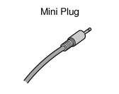
| Mini Plug (for pager and music source) |
|
|
| |
|
|
|
|
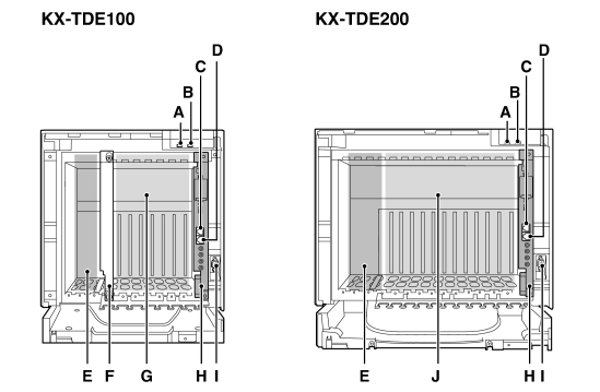
3.2.2 Names and Locations
Inside View
| A. |
RUN Indicator |
| B. |
ALARM Indicator |
| C. |
MNT Port |
| D. |
LAN Port |
| E. |
PSU Slot |
| F. |
Null Slot (not available for any optional service card) |
| G. |
Free Slots 1 to 6 (from the left) |
| H. |
IPCMPR Card Slot |
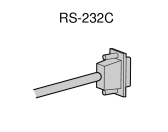
| I. |
RS-232C Port |
| J. |
Free Slots 1 to 11 (from the left) |
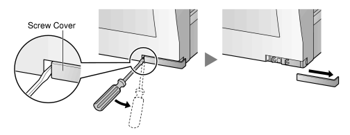
3.2.3 Opening/Closing the Front Cover
Opening the Front Cover
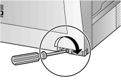
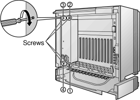
| 1. |
Insert a flathead screwdriver into the opening (on the left of the screw cover) and unlatch the screw cover. |
|
|
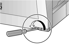
| 2. |
Turn the screw anticlockwise to loosen. |
|
|
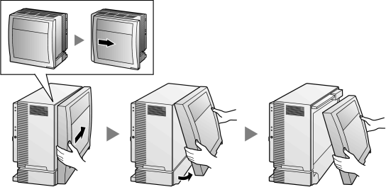
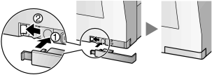
| 3. |
Slide the front cover to the right until it stops, then lift the front cover. |
|
|
Closing the Front Cover
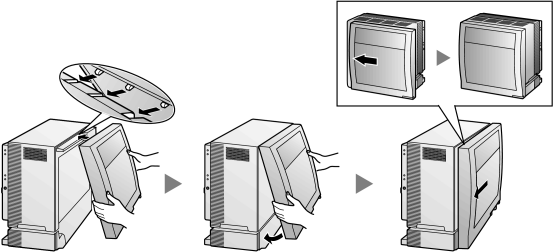
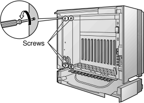
| 1. |
Hook the front cover onto the shelf (line up the protrusions on the cover with the receptacles on the shelf). Then slide the front cover to the left until it locks. |
|
|
| 2. |
Turn the screw clockwise to tighten. |
|
|
| 3. |
Secure the screw cover. |
|
|
CAUTION
|
• |
For safety reasons, close the front cover and tighten the screw before operating the PBX. |
|
• |
Do not forget to tighten the screw before securing the screw cover. |
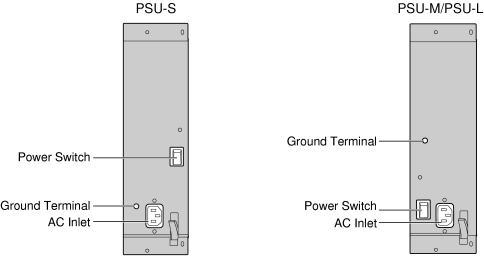
3.2.4 Installing/Replacing the Power Supply Unit
Function
|
PSU Type |
Lower/Upper Input Voltage Range |
Current |
Input Frequency |
|
|
| Lower: 100 V AC to 130 V AC |
|
|
|
| Upper: 200 V AC to 240 V AC |
|
|
PSU-M
(for KX-TDE100/KX-TDE200) |
|
| Lower: 100 V AC to 130 V AC |
|
|
| Upper: 200 V AC to 240 V AC |
|
|
|
|
| Lower: 100 V AC to 130 V AC |
|
|
| Upper: 200 V AC to 240 V AC |
|
|
|
Accessories and User-supplied Items
|
| Accessories (included): Screws × 4, AC power cord × 1 |
| User-supplied (not included): Grounding wire |
|
Safety Instructions
|
Each PSU complies with Safety Class 1 of IEC60950, EN60950, UL60950,
CAN/CSA-C22.2 No.60950, and AS/NZS60950; therefore a protective ground connection exists between the mains outlet ground and the PSU case. To ensure the PBX chassis is safely grounded, it is essential that the PSU case be securely fastened to the PBX chassis with the 4 screws provided with each PSU. |
| When installing or replacing a PSU, basic safety precautions should always be followed to reduce the risk of fire, electric shock and injury to persons, including the following: |
| 1. |
Never install or replace a PSU during a lightning storm. |
| 2. |
Never install or replace a PSU in wet locations. |
| 3. |
Never install or replace a PSU unless at least 20 s has elapsed after the AC supply is disconnected. |
| 4. |
To protect the back board from static electricity, do not touch parts on the back board in the main unit and PSU. To discharge static electricity, touch ground or wear a grounding strap. |
|
The following procedures are for installing or replacing a PSU only. Do not replace or remove the PSU for any other purpose. |
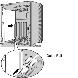
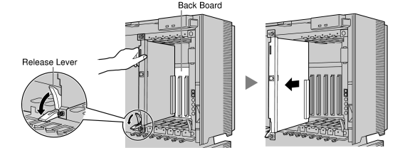
Installing the Power Supply Unit
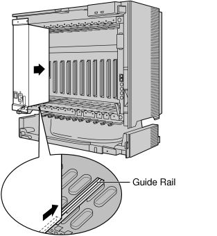
| 1. |
Insert the PSU along the guide rails. |
|
CAUTION
|
For safety reasons, do not touch parts in the PSU. |
|
|
|
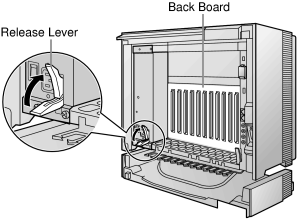
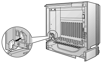
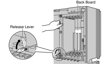
| 2. |
Push the release lever in the direction of the arrow, so that the PSU engages securely with the connector on the back board. |
|
|
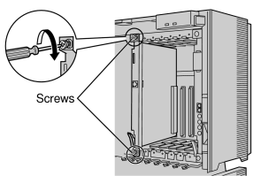
| 3. |
Turn the 4 screws clockwise, in the order indicated by the numbers 1 to 4, to fix the PSU. |
|
|
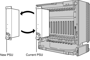
Replacing the Power Supply Unit
| 1. |
Unplug the AC power cord. |
|
|
| 2. |
Turn the 4 screws anticlockwise to loosen them. |
|
|
| 3. |
Pull the release lever in the direction of the arrow to disconnect the PSU from the back board. |
|
|
| 4. |
Replace the PSU. |
|
|
| 5. |
Follow the steps in "Installing the Power Supply Unit". |
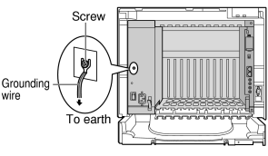
3.2.5 Frame ground Connection
IMPORTANT
|
Connect the frame of the PBX to ground. |
| 1. |
Loosen the screw. |
| 2. |
Insert a grounding wire (user-supplied)*. |
| 3. |
Tighten the screw. |
| 4. |
Connect the grounding wire to ground. |
|
|
|
|
| For grounding wire, green-and-yellow insulation is required, and the cross-sectional area of the conductor must be more than 0.75 mm2 or 18 AWG. |
|
| • |
Be sure to comply with applicable local regulations (e.g., laws, guidelines). |
| • |
Proper grounding (connection to ground) is very important to protect the PBX from the bad effects of external noise or to reduce the risk to the user of electrocution in the case of a lightning strike. |
| • |
The grounding wire of the AC cable has an effect against external noise and lightning strikes, but it may not be enough to protect the PBX. A permanent connection between ground and the ground terminal of the PBX must be made. |
In most of the continental United States, the ground provided by the "Third wire ground" at the commercial power outlet will be satisfactory. However, in a small percentage of cases this ground may be installed incorrectly. Therefore, the following test procedure should be performed. |
Test Procedure
| 1. |
Obtain a suitable voltmeter and set it for a possible reading of up to 250 V AC. |
| 2. |
Connect the meter probes between the 2 main AC voltage points on the wall outlet. The reading obtained should be 108 V AC to 132 V AC. |
| 3. |
Move one of the meter probes to the 3rd prong terminal (GND).
Either the same reading or a reading of 0 volt should be obtained. |
| 4. |
If a reading of 0 volt at one terminal and a reading of 108 V AC to 132 V AC at the other terminal is not obtained, the outlet is not properly grounded.
This condition should be corrected by a qualified electrician (per article 250 of the National Electrical Code). |
| 5. |
If a reading of 0 volt at one terminal and a reading of 108 V AC to 132 V AC at the other terminal is obtained, then set the meter to the "OHMS/RX1" scale, place one probe at the GND Terminal and the other probe at the terminal which gave a reading of 0 volt.
A reading of less than 1 ohm should be obtained. If the reading is not obtained, the outlet is not adequately grounded. See qualified electrician. |
|
3.2.6 Installing/Removing the Optional Service Cards
CAUTION
|
To protect the back board from static electricity, do not touch parts on the back board in the main unit and on the optional service cards. To discharge static electricity, touch ground or wear a grounding strap. |
Note
|
The optional service cards can be installed or removed while the DC power is supplied. However, when installing or removing the IPCMPR card, the DC power supply must be turned off. |
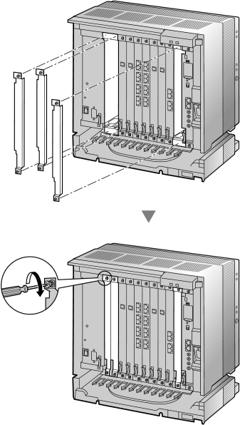
Installing Optional Service Cards
| 1. |
Insert the card along the guide rails. |
|
|
| 2. |
Holding the card as shown below, push the release lever in the direction of the arrow so that the card engages securely with the connector on the back board. |
|
|
| 3. |
Turn the 2 screws clockwise to fix the card in place. |
|
|
|
Note
|
Make sure the screws are tightened to ground the card securely. |
|
|
Covering the Blank Slots
|
| Be sure to cover each slot in which no optional service card is installed by using a Blank Slot Cover. |
CAUTION
|
Failure to install the Blank Slot Cover may cause electromagnetic interference. |
|
|
|
|
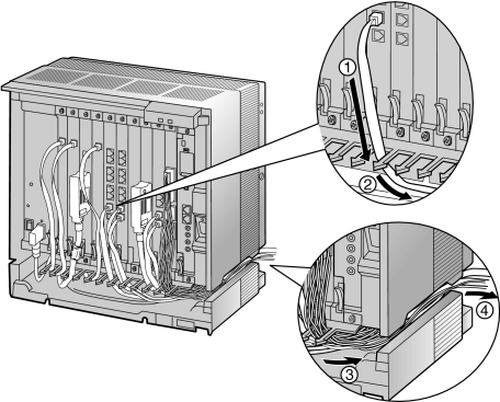
Handling of the Cables
|
| When cables are connected to the PBX, run the cables to either the right or the left and then towards the back of the shelf as shown below. |
|
|
Note
|
For safety reasons, do not stretch, bend, or pinch the AC power cord. |
|
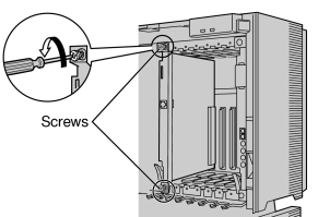
Removing the Optional Service Cards
| 1. |
Turn the 2 screws anticlockwise to loosen them. |
|
|
| 2. |
Pull the release lever in the direction of the arrow to disconnect the card from the back board. Pull the card from the shelf to remove it. |
|
|
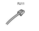
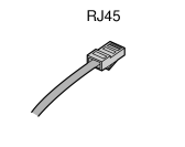
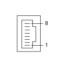
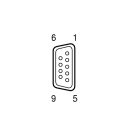
3.2.7 Types of Connectors
|
Connector Type |
Pin Number |
Used for |
|
|
|
| • |
DHLC8 (KX-TDA0170) |
| • |
SLC8 (KX-TDA0173) |
| • |
SLC16 (KX-TDA0174) |
| • |
MSLC16 (KX-TDA0175) |
| • |
CSLC16 (KX-TDA0177) |
| • |
LCOT8 (KX-TDA0180) |
| • |
LCOT16 (KX-TDA0181) |
|
|
|
|
| • |
IPCMPR |
| • |
CSIF4 (KX-TDA0143) |
| • |
CSIF8 (KX-TDA0144) |
| • |
T1 (KX-TDA0187) |
| • |
PRI23 (KX-TDA0290) |
| • |
IP-EXT16 (KX-TDA0470) |
| • |
IP-GW4E (KX-TDA0484) |
| • |
IP-GW16 (KX-TDA0490) |
|
|
|
| (Shielded twisted pair cable) |
|
|
| • |
DHLC8 (KX-TDA0170) |
| • |
DLC8 (KX-TDA0171) |
| • |
DLC16 (KX-TDA0172) |
| • |
SLC8 (KX-TDA0173) |
| • |
SLC16 (KX-TDA0174) |
| • |
MSLC16 (KX-TDA0175) |
| • |
CSLC16 (KX-TDA0177) |
| • |
LCOT8 (KX-TDA0180) |
| • |
LCOT16 (KX-TDA0181) |
|
|
|
|
| • |
DPH4 (KX-TDA0161) |
| • |
EIO4 (KX-TDA0164) |
|
|
|
|
|
|
|
|
|
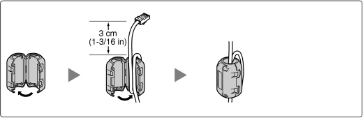
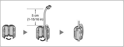
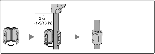
3.2.8 Attaching a Ferrite Core
| A ferrite core must be attached when: |
| • |
an RJ45 connector is connected to an IPCMPR, IP-GW16 or IP-EXT16 cards, or |
| • |
an Amphenol connector is connected to an extension card. |
|
Attaching to an RJ45 Connector
|
For the IPCMPR Card
|
| Wrap the cable once around the ferrite core, then close the case of the ferrite core. Attach the ferrite core 3 cm (1-3/16 in) away from the connector. The ferrite core is included with the PBX. |
|
|
|
For IP-GW16/IP-EXT16 Cards
|
| Wrap the cable once around the ferrite core, then close the case of the ferrite core. Attach the ferrite core 5 cm (1-15/16 in) away from the connector. The ferrite core is included with the card. |
|
|
Attaching to an Amphenol Connector
|
For Extension Cards
|
| Pass the cable through the ferrite core, then close the case of the ferrite core. Attach the ferrite core 3 cm (1-3/16 in) away from the connector. The ferrite core is included with the card. |
|
|
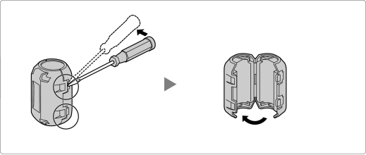
If you need to open the ferrite core, use a flathead screwdriver to unlatch the case of the ferrite core. |
|
|
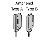
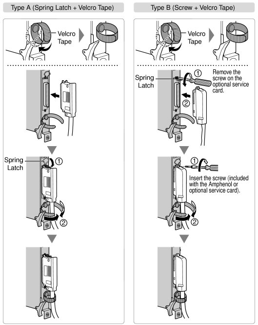
3.2.9 Fastening an Amphenol Connector
An Amphenol 57JE-type connector is used on some of the optional service cards.
To connect an Amphenol connector, use the spring latch or screw to fix the upper part and use Velcro tape to fix the lower part of the connector. tape to fix the lower part of the connector. |
|
|
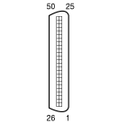
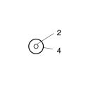
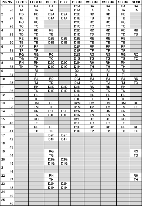
Amphenol Connector Pin Assignment Chart
3.2.10 Wall Mounting (KX-TDE200)
WARNING
|
• |
MAKE SURE THAT THE WALL THAT THE SHELF WILL BE ATTACHED TO IS STRONG ENOUGH TO SUPPORT THE SHELF. IF NOT, IT IS NECESSARY FOR THE WALL TO BE REINFORCED. |
|
• |
ONLY USE THE WALL-MOUNTING EQUIPMENT (ANCHOR PLUGS, SCREWS, METAL BRACKET) INCLUDED WITH THE PBX. |
|
• |
WHEN DRIVING THE SCREWS INTO THE WALL, BE CAREFUL TO AVOID TOUCHING ANY METAL LATHS, WIRE LATHS OR METAL PLATES IN THE WALL. |
|
• |
WHEN PLACING THE METAL BRACKET, MAKE SURE THAT THE "TOP" ARROW IS POINTING UPWARD. |
|
• |
WHEN THIS PRODUCT IS NO LONGER IN USE, MAKE SURE TO DETACH IT FROM THE WALL. |
Notes
|
• |
Do not block the openings of the shelf. Allow space of at least 20 cm (8 in) above and 10 cm (4 in) at the sides of the shelf. |
|
• |
Make sure that the surface behind the shelf is flat and free of obstacles, so that the openings on the back of the shelf will not be blocked. |
|
• |
Make sure that the surface behind the shelf is not made of wood. |
|
• |
Be careful not to drop the shelf. |
|
• |
For details about the dimensions and weight of the PBX, refer to "1.4.1 General Description". |
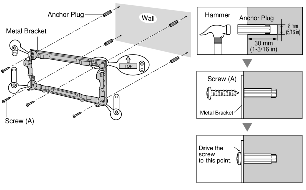
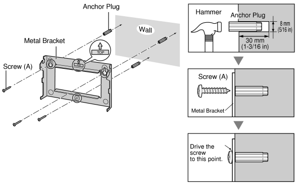
| 1. |
Install 4 anchor plugs in the wall, using the metal bracket as a template. Fix the metal bracket with 4 screws (A). |
|
|
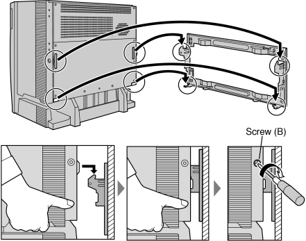
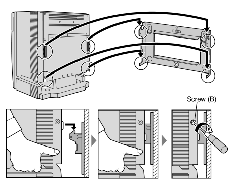
| 2. |
Hook the shelf onto the metal bracket, making sure that the shelf slides down and onto the hooked parts of the metal bracket. Use 2 screws (B) to fix both sides of the shelf. |
|
|
3.2.11 Wall Mounting (KX-TDE100)
WARNING
|
• |
MAKE SURE THAT THE WALL THAT THE SHELF WILL BE ATTACHED TO IS STRONG ENOUGH TO SUPPORT THE SHELF. IF NOT, IT IS NECESSARY FOR THE WALL TO BE REINFORCED. |
|
• |
ONLY USE THE WALL-MOUNTING EQUIPMENT (ANCHOR PLUGS, SCREWS, METAL BRACKET) INCLUDED WITH THE PBX. |
|
• |
WHEN DRIVING THE SCREWS INTO THE WALL, BE CAREFUL TO AVOID TOUCHING ANY METAL LATHS, WIRE LATHS OR METAL PLATES IN THE WALL. |
|
• |
WHEN PLACING THE METAL BRACKET, MAKE SURE THAT THE "TOP" ARROW IS POINTING UPWARD. |
|
• |
WHEN THIS PRODUCT IS NO LONGER IN USE, MAKE SURE TO DETACH IT FROM THE WALL. |
Notes
|
• |
Do not block the openings of the shelf. Allow space of at least 20 cm (8 in) above and 10 cm (4 in) at the sides of the shelf. |
|
• |
Make sure that the surface behind the shelf is flat and free of obstacles, so that the openings on the back of the shelf will not be blocked. |
|
• |
Make sure that the surface behind the shelf is not made of wood. |
|
• |
Be careful not to drop the shelf. |
|
• |
For details about the dimensions and weight of the PBX, refer to "1.4.1 General Description". |
| 1. |
Install 3 anchor plugs in the wall, using the metal bracket as a template. Fix the metal bracket with 3 screws (A). |
|
|
| 2. |
Hook the shelf onto the metal bracket, making sure that the shelf slides down and onto the hooked parts of the metal bracket. Use 2 screws (B) to fix both sides of the shelf. |
|
|
3.2.12 Floor Standing (KX-TDE200 Only)
Notes
|
• |
Do not block the openings of the shelf. Allow space of at least 20 cm (8 in) above and 10 cm (4 in) at the sides of the shelf. |
|
• |
Make sure that the surface behind the shelf is flat and free of obstacles, so that the openings on the back of the shelf will not be blocked. |
|
• |
Make sure that the surface behind the shelf is not made of wood. |
|
• |
Be careful not to drop the shelf. |
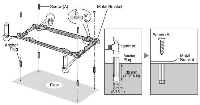
| 1. |
Install 4 anchor plugs in the floor, using the metal bracket as a template. Fix the metal bracket with 4 screws (A). |
|
|
| 2. |
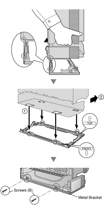
Remove the front cover of the shelf (refer to "3.2.3 Opening/Closing the Front Cover"). |
| 3. |
Lift the shelf, attach it to the metal bracket, slide it backwards until it locks, and retain it with 2 screws (B).
|
|
|
| 4. |
Fix the front cover on the shelf (refer to "3.2.3 Opening/Closing the Front Cover"). |
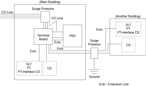
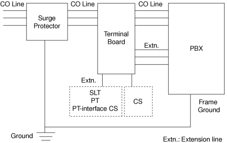
3.2.13 Surge Protector Installation
Overview
A massive electrical surge can be caused if lightning strikes a telephone cable 10 m (33 ft) above ground, or if a telephone line comes into contact with a power line. A surge protector is a device that is connected to a CO line to prevent potentially dangerous electrical surges from entering the building via the CO line and damaging the PBX and connected equipment.
|
| To protect the system from electrical surges, we strongly recommend connecting the system to a surge protector that meets the following specifications: |
| – |
Surge arrestor type: 3-electrode arrestor |
| – |
DC spark-over voltage: 230 V |
| – |
Maximum peak current: at least 10 kA |
| Many countries/areas have regulations requiring surge protection. Be sure to comply with all applicable laws, regulations, and guidelines. |
Outside Installation
| If you install an extension outside of the building, the following precautions are recommended: |
| a. |
Install the extension wire underground. |
| b. |
Use a conduit to protect the wire. |
|
Note
|
The surge protector for an extension and CS is different from that for CO lines. |
|
|
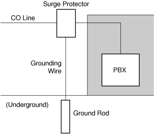
Installation of a ground Rod
| 1. |
Connect the ground rod to the surge protector using a grounding wire with a cross-sectional area of at least 1.3 mm2. |
| 2. |
Bury the ground rod near the protector. The grounding wire should be as short as possible. |
| 3. |
The grounding wire should run straight to the ground rod. Do not run the wire around other objects. |
| 4. |
Bury the ground rod at least 50 cm (20 in) underground. |
|
Notes
|
• |
The above figures are recommendations only. |
|
• |
The length of ground rod and the required depth depend on the composition of the soil. |
|