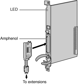
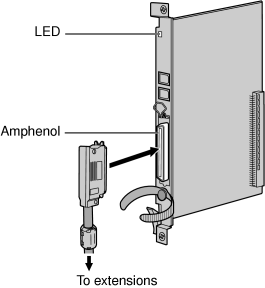
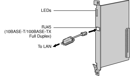
3.6 Information about the Physical Extension Cards
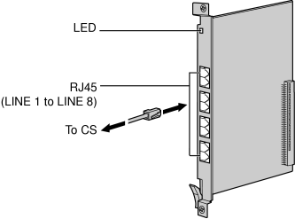
3.6.1 CSIF4 Card (KX-TDA0143) and CSIF8 Card (KX-TDA0144)
Function
|
Accessories and User-supplied Items
|
| Accessories (included): none |
| User-supplied (not included): RJ45 connector |
CAUTION
|
Make sure that the status of all the CSs connected to the CSIF cards are set to in-service (INS). For information about how to view CS information using the Maintenance Console, refer to "2.6.15 UtilityCS Information" in the PC Programming Manual. If there is a CS in out-of-service (OUS) status, make sure that it is securely connected to the CSIF card. If the CS remains in OUS status, there may be a fault with the connection. Do not leave the connected CS in OUS status since it may cause severe damage to the CSIF card. |
|
Editing the CS Name using the Maintenance Console
|
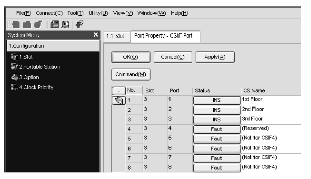
| While programming the PBX, we strongly recommend that you input a unique recognizable CS name (maximum 20 characters) for each CS port in use, and "(Reserved)" or "(Not for CSIF4)" for unused ports or unavailable ports respectively for the following reasons: |
| a. |
you will be able to easily distinguish installed CSs. |
| b. |
you will be able to know which CSIF card has been installed; CSIF4 or CSIF8.
|
|
Example: When the CSIF4 card has been installed  |
|
LED Indications
|
Indication |
Color |
Description |
|
|
|
| • |
OFF: Power Off |
| • |
Green ON: Normal (all ports are idle) |
| • |
Green Flashing (60 times per minute): Normal (a port is in use) |
| • |
Red ON: Fault (includes reset) |
| • |
Red Flashing (60 times per minute): Out of Service |
|
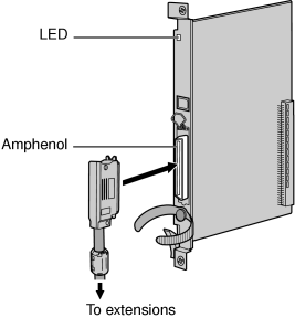
3.6.2 DHLC8 Card (KX-TDA0170)
Function
|
Accessories and User-supplied Items
|
| Accessories (included): Screws Χ 2, Ferrite core Χ 1 |
| User-supplied (not included): Amphenol connector |
Pin Assignments
|
Amphenol Connector
|
| |
No. |
Signal Name |
Function |
No. |
Signal Name |
Function | |
|
|
|
|
|
|
| |
|
|
|
|
|
| |
|
|
|
|
|
| |
|
|
|
|
|
| |
|
|
|
|
|
| |
|
|
|
|
|
| |
|
|
|
|
|
| |
|
|
|
|
|
| |
|
|
|
|
|
| |
|
|
|
|
|
| |
|
|
|
|
|
| |
|
|
|
|
|
| |
|
|
|
|
|
| |
|
|
|
|
|
| |
|
|
|
|
|
| |
|
|
|
|
|
| |
|
|
|
|
|
| |
|
|
|
|
|
| |
|
|
|
|
|
| |
|
|
|
|
|
| |
|
|
|
|
|
| |
|
|
|
|
|
| |
|
|
|
|
|
| |
|
|
|
|
|
|
|
LED Indications
|
Indication |
Color |
Description |
|
|
|
| • |
OFF: Power Off |
| • |
Green ON: Normal (all ports are idle) |
| • |
Green Flashing (60 times per minute): Normal (a port is in use) |
| • |
Orange Flashing: Detection of PT-interface CS connection (when starting up the PT-interface CS [Basic/High-density]) |
| • |
Red ON: Fault (includes reset) |
| • |
Red Flashing (60 times per minute): Out of Service |
|
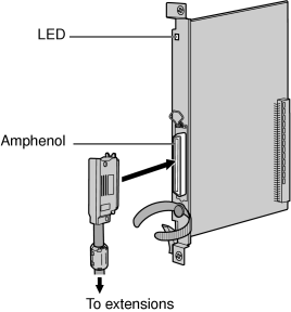
3.6.3 DLC8 Card (KX-TDA0171)
Function
|
Accessories and User-supplied Items
|
| Accessories (included): Screws Χ 2, Ferrite core Χ 1 |
| User-supplied (not included): Amphenol connector |
Pin Assignments
|
Amphenol Connector
|
| |
No. |
Signal Name |
Function |
No. |
Signal Name |
Function | |
|
|
|
|
|
|
| |
|
|
|
|
|
| |
|
|
|
|
|
| |
|
|
|
|
|
| |
|
|
|
|
|
| |
|
|
|
|
|
| |
|
|
|
|
|
| |
|
|
|
|
|
| |
|
|
|
|
|
| |
|
|
|
|
|
| |
|
|
|
|
|
| |
|
|
|
|
|
| |
|
|
|
|
|
| |
|
|
|
|
|
| |
|
|
|
|
|
| |
|
|
|
|
|
| |
|
|
|
|
|
|
|
LED Indications
|
Indication |
Color |
Description |
|
|
|
| • |
OFF: Power Off |
| • |
Green ON: Normal (all ports are idle) |
| • |
Green Flashing (60 times per minute): Normal (a port is in use) |
| • |
Orange Flashing: Detection of PT-interface CS connection (when starting up the PT-interface CS [Basic/High-density]) |
| • |
Red ON: Fault (includes reset) |
| • |
Red Flashing (60 times per minute): Out of Service |
|
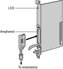
3.6.4 DLC16 Card (KX-TDA0172)
Function
|
Accessories and User-supplied Items
|
| Accessories (included): Screws Χ 2, Ferrite core Χ 1 |
| User-supplied (not included): Amphenol connector |
Pin Assignments
|
Amphenol Connector
|
| |
No. |
Signal Name |
Function |
No. |
Signal Name |
Function | |
|
|
|
|
|
|
| |
|
|
|
|
|
| |
|
|
|
|
|
| |
|
|
|
|
|
| |
|
|
|
|
|
| |
|
|
|
|
|
| |
|
|
|
|
|
| |
|
|
|
|
|
| |
|
|
|
|
|
| |
|
|
|
|
|
| |
|
|
|
|
|
| |
|
|
|
|
|
| |
|
|
|
|
|
| |
|
|
|
|
|
| |
|
|
|
|
|
| |
|
|
|
|
|
| |
|
|
|
|
|
|
|
LED Indications
|
Indication |
Color |
Description |
|
|
|
| • |
OFF: Power Off |
| • |
Green ON: Normal (all ports are idle) |
| • |
Green Flashing (60 times per minute): Normal (a port is in use) |
| • |
Orange Flashing: Detection of PT-interface CS connection (when starting up the PT-interface CS [Basic/High-density]) |
| • |
Red ON: Fault (includes reset) |
| • |
Red Flashing (60 times per minute): Out of Service |
|
3.6.5 SLC8 Card (KX-TDA0173)
Function
|
Accessories and User-supplied Items
|
| Accessories (included): Screws Χ 2, Ferrite core Χ 1 |
| User-supplied (not included): Amphenol connector |
Pin Assignments
|
Amphenol Connector
|
| |
No. |
Signal Name |
Function |
No. |
Signal Name |
Function | |
|
|
|
|
|
|
| |
|
|
|
|
|
| |
|
|
|
|
|
| |
|
|
|
|
|
| |
|
|
|
|
|
| |
|
|
|
|
|
| |
|
|
|
|
|
| |
|
|
|
|
|
| |
|
|
|
|
|
| |
|
|
|
|
|
| |
|
|
|
|
|
| |
|
|
|
|
|
| |
|
|
|
|
|
| |
|
|
|
|
|
| |
|
|
|
|
|
| |
|
|
|
|
|
|
|
LED Indications
|
Indication |
Color |
Description |
|
|
|
| • |
OFF: Power Off |
| • |
Green ON: Normal (all ports are idle) |
| • |
Green Flashing (60 times per minute): Normal (a port is in use) |
| • |
Red ON: Fault (includes reset) |
| • |
Red Flashing (60 times per minute): Out of Service |
|
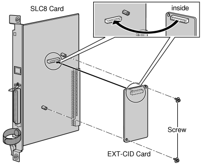
3.6.6 EXT-CID Card (KX-TDA0168)
Function
|
Accessories and User-supplied Items
|
| Accessories (included): Screws Χ 2 |
| User-supplied (not included): none |
3.6.7 SLC16 Card (KX-TDA0174), MSLC16 Card (KX-TDA0175), and CSLC16 Card (KX-TDA0177)
Function
|
Accessories and User-supplied Items
|
| Accessories (included): Screws Χ 2, Ferrite core Χ 1 |
| User-supplied (not included): Amphenol connector |
Pin Assignments
|
Amphenol Connector
|
| |
No. |
Signal Name |
Function |
No. |
Signal Name |
Function | |
|
|
|
|
|
|
| |
|
|
|
|
|
| |
|
|
|
|
|
| |
|
|
|
|
|
| |
|
|
|
|
|
| |
|
|
|
|
|
| |
|
|
|
|
|
| |
|
|
|
|
|
| |
|
|
|
|
|
| |
|
|
|
|
|
| |
|
|
|
|
|
| |
|
|
|
|
|
| |
|
|
|
|
|
| |
|
|
|
|
|
| |
|
|
|
|
|
| |
|
|
|
|
|
| |
|
|
|
|
|
|
|
LED Indications
|
Indication |
Color |
Description |
|
|
|
| • |
OFF: Power Off |
| • |
Green ON: Normal (all ports are idle) |
| • |
Green Flashing (60 times per minute): Normal (a port is in use) |
| • |
Red ON: Fault (includes reset) |
| • |
Red Flashing (60 times per minute): Out of Service |
|
3.6.8 IP-EXT16 Card (KX-TDA0470)
Function
|
Accessories and User-supplied Items
|
| Accessories (included): Ferrite core Χ 1 |
| User-supplied (not included): RJ45 connector |
Notes
|
• |
The maximum length of the cable to be connected to this optional service card is 100 m (328 ft). |
|
• |
When connecting the RJ45 connector, attach the included ferrite core. Refer to "3.2.8 Attaching a Ferrite Core". |
Pin Assignments
|
RJ45 Connector (10BASE-T/100BASE-TX)
|
| |
No. |
Signal Name |
Input (I)/Output (O) |
Function | |
|
|
|
|
| |
|
|
|
| |
|
|
|
| |
|
|
|
| |
|
|
|
| |
|
|
|
|
|
LED Indications
|
Indication |
Color |
Description |
|
|
|
| • |
OFF: Power Off |
| • |
Green ON: Normal (all ports are idle) |
| • |
Green Flashing (60 times per minute): Normal (a port is in use) |
| • |
Red ON: Fault (includes reset) |
| • |
Red Flashing (60 times per minute): Out of Service |
|
|
|
|
| On-line status indication |
| • |
ON: At least one port is in use (an IP-PT is connected) |
| • |
OFF: No ports are in use (no IP-PTs are connected) |
Note
|
If the LINK indicator is OFF, the ONLINE indicator will also be OFF. |
|
|
|
|
| • |
OFF: Normal |
| • |
ON: Alarm |
|
|
|
|
| Panasonic proprietary VoIP protocol process indication |
| • |
OFF: VoIP process inactive |
| • |
ON: VoIP process active |
|
|
|
|
| • |
OFF: Connection error |
| • |
ON: Normal connection |
|
|
|
|
| Data transmission indication |
| • |
OFF: No data transmitted |
| • |
ON: Data transmitting |
|

