5.1 Troubleshooting

5.1.1 Installation

PROBLEM

PROBABLE CAUSE

SOLUTION

You cannot make/receive calls via an IP network.
IP-EXT/IP-GW/DSP card malfunction
Replace the corresponding card.
 
IPCMPR card malfunction
Replace the IPCMPR card (be sure to turn off the PBX when replacing).
 
Not enough activation keys
Purchase additional activation key codes. Please consult a certified dealer for details.
 
Poor connection
Make sure that an 8-pin twisted pair cable is used for connection.
Make sure that none of the CAT 5 cables in use are over 100 m (328 ft) in length.
Make sure that a straight cable is used for connection to a switching hub.
 
Network malfunction
Make sure that all network devices in use are switched on.
Make sure that there is no unwanted firewall in the IP network.
IP-PTs/SIP Extensions do not operate.
IP-EXT/DSP card malfunction
Replace the corresponding card.
 
IPCMPR card malfunction
Replace the IPCMPR card (be sure to turn off the PBX when replacing).
 
Not enough activation keys
Purchase additional activation key codes. Please consult a certified dealer for details.
 
IP-PT/SIP Extension not registered
Register the corresponding IP-PT/SIP Extension.
 
IP-PT/SIP Extension malfunction
Replace the IP-PT/SIP Extension.
 
Poor connection
Make sure that an 8-pin twisted pair cable is used for connection.
Make sure that none of the CAT 5 cables in use are over 100 m (328 ft) in length.
Make sure that a straight cable is used for connection to a switching hub.
 
Network malfunction
Make sure that all network devices in use are switched on.
Make sure that the IP-PT/SIP Extension is not blocked by the firewall or other network devices.
Extensions (except IP-PT/SIP Extension) do not operate.
Extension card malfunction
Replace the corresponding card.
 
Poor connection between the PBX and the extension
Take the extension and plug it into the same extension port using a short telephone cord. If the extension works, then the connection between the PBX and the extension must be repaired.
 
A telephone with an A-A1 relay is connected.
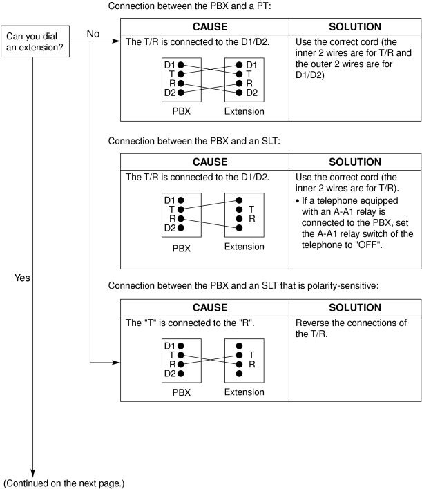
Make sure that a 2-wire cord is used.
Make sure that the A-A1 relay switch of the telephone is in "OUT" or "OFF" position.
 
Extension malfunction
Take the extension and plug it into another extension port that is working. If the extension does not work, replace the extension.
 
Wrong type of PSU
Replace the PSU with the appropriate type.
The PBX does not operate properly.
 
Press the Reset Button (refer to "5.1.4 Using the Reset Button").
Turn off the power switch, and then turn it back on.
Turn off the power switch, and then unplug the PBX. After 5 minutes, plug the PBX back in, and turn the power switch back on.
Noise on external paging.
Induced noise on the wire between the PBX and the amplifier.
Use a shielded cable as the connection wire between the PBX and amplifier. A short shielded cable is recommended.
Distorted external music.
Excessive input level from external music source.
Decrease the output level of the external music source by using the volume control on the music source.
Alternate Calling—Ring/Voice and Live Call Screening (LCS) do not function as set when using a Wireless Phone (KX-T7880/KX-T7885/KX-TD7894/KX-TD7895).
Voice-calling mode and Hands-free mode with LCS are not available with Wireless Phones.
Switch the calling mode to ring-calling.
Set the LCS mode to "Private".
The ALARM indicator on the front of the shelf turns on red.
A major system error occurs in the PBX.
See the error log using the Maintenance Console (refer to "5.1.5 Troubleshooting by Error Log").
The LINK indicator of the IP-EXT/IP-GW/IPCMPR does not turn on.
IP-EXT/IP-GW card malfunction
Replace the corresponding card.
IPCMPR card malfunction
Replace the IPCMPR card (be sure to turn off the PBX when replacing).
Poor connection
Make sure that an 8-pin twisted pair cable is used for connection.
Make sure that none of the CAT 5 cables in use are over 100 m (328 ft) in length.
Make sure that a straight cable is used for connection to a switching hub.
Network malfunction
Make sure that all network devices in use are switched on.

5.1.2 Connection

IMC4010a.gif
IMC4015a.gif

5.1.3 Operation

PROBLEM

PROBABLE CAUSE

SOLUTION

Cannot set the IP address, subnet mask address, and PBX IP address to the IP-PT.
An unusable value is being set.
Set an IP address within the valid range. IP address of the IP-PT/PBX: "1.0.0.0" to "223.255.255.255" Subnet mask address: "0–255.0–255.0–255.0–255" (except 0.0.0.0 and 255.255.255.255)
Cannot register the IP-PT.
The necessary network parameters are not set to the IP-PT.
When not using a DHCP server, set the IP address, subnet mask address, and enter the PBX IP address. If necessary, also enter the IP address of the default gateway.
When using a DHCP server, enter the PBX IP address.
The IP-PT cannot connect to the PBX.
The wrong IP address, subnet mask address, PBX IP address, or default gateway address was entered.
Check each parameter and enter the correct value.
 
The Ethernet cable is not connected correctly.
Check the Ethernet cable connections.
 
The DHCP server is not active.
Restart the DHCP server.
Disable DHCP and re-enter settings as appropriate.
When using the speakerphone on an APT, nothing is audible.
The HANDSET/HEADSET selector is set to the "HEADSET" position.
When the headset is not used, set the HANDSET/HEADSET selector to the "HANDSET" position.
When using the speakerphone/monitor mode with a DPT, nothing is audible.
The "HEADSET" mode is selected by Personal Programming, "Handset/Headset Selection".
When the headset is not used, select the "HANDSET" mode by Personal Programming.
The PT does not ring.
The ringer volume is off.
Turn on the ringer volume.
During a power failure, extensions connected to ports 1 to 4 of MSLC16/CSLC16/SLC16 and ports 1 to 2 of DHLC8/SLC8 cards do not operate.
A DPT or APT is connected to the extension port.
The dialing mode (tone or pulse) is incorrect.
Disconnect the DPT or APT and connect an SLT.
Set the Tone/Pulse switch to the other position.
Originating an outside call, call transfer, or conference cannot be performed.
The corresponding flexible button does not exist on the PT.
Program the flexible button. Refer to "1.6.3 Flexible Buttons" in the Feature Manual.
The LED of the CS does not change to Green ON.
CS is not connected properly.
Make sure that the cable is connected properly with correct pin assignments. Also, make sure that the cable does not make short circuits.
CS is not set for normal operation.
Switch all DIP switches off.
The status of the port that the CS is connected to is Out of Service.
Change the port status from Out of Service to In Service using the Maintenance Console.
<KX-T0158 only>
The Local Processor (LPR) software of the corresponding DHLC/DLC card is not version 5.000 or later.
 
Upgrade the LPR software of the DHLC/DLC card.
<KX-T0158 only>
Both KX-T0158 and KX-T0155 CSs are connected to the same card, and the KX-T0158 CSs are connected to higher-numbered pins on the card than the KX-T0155 CSs.
 
Connect the KX-T0158 CSs to lower-numbered pins on the card than the KX-T0155 CSs.
Connect the KX-T0158 and KX-T0155 CSs to different cards.
The LED of the CS stays Red ON during normal operation.
CS malfunction
Replace the CS.
"CLEAR SCAN DATA" is displayed on the PS's screen after turning on the PS.
The PS cannot be used for normal operation when scan data is stored on the PS.
Clear the scan data (refer to "3.10.5 Site Survey").
Cannot register the PS.
Wrong Personal Identification Number (PIN) is registered to the PS.
Enter the PIN set to the PBX into the PS.
PS becomes out of range.
CSIF card is not working.
Install the CSIF card properly.
Cannot make calls using the PS.
CS is not working.
Make sure that the cable is connected properly with correct pin assignments. Also, make sure that the cable does not make short circuits.
Switch all DIP switches off.
 
Location of CS is not good.
Locate the CS properly (refer to "3.9.5 Site Survey" or "3.10.5 Site Survey").
 
Access system of the PS is not properly set.
Change the access system setting of the PS to the appropriate system or automatic.
Noise is frequent while using the PS.
Conversations disconnect while using the PS.
"NO SERVICE" is displayed on the PS's screen.
Call handover is not working.
PS is out of CS coverage area.
Locate the CS properly (refer to "3.9.5 Site Survey" or "3.10.5 Site Survey").
The CS is not busy (i.e., the status of the LED is not Moderate Green Flashing), but calls cannot be made or received.
There is noise during a phone call.
CSs are located too close together in the same area.
Reduce the number of CSs in the area, or increase the distance between CSs (refer to "3.9.5 Site Survey" or "3.10.5 Site Survey").
PS stays out of service when the CS status is changed from Out of Service to In Service.
It may take about 20 s for CS to start up after the status has been changed to In Service.
Wait until the CS starts up.
The maximum number of PS calls that a high-density CS supports cannot be made.
Poor connection
Make sure that a 4-pair cable is used for connection.

5.1.4 Using the Reset Button

If the PBX does not operate properly, use the Reset Button. Before using the Reset Button, try the system feature again to confirm whether there definitely is a problem or not.
CAUTION
In order to avoid possible corruption of data on the SD Memory Card, please ensure that the "SD ACCESS" LED is off before pressing the Reset Button.
Notes
When the System Initialize Switch is set to "NORMAL", pressing the Reset Button causes the following:
Camp-on is cleared.
Calls on hold are terminated.
Calls on exclusive hold are terminated.
Calls in progress are terminated.
Call park is cleared.
Other data stored in memory, except the above, are not cleared.
Be aware that pressing the Reset Button with the System Initialize Switch in the "SYSTEM INITIALIZE" position clears all data stored in the PBX. Do not perform this operation unless you intend to delete all data from the PBX.

Operation

If the PBX does not operate properly:
1. Slide the System Initialize Switch to the "NORMAL" position.
2. Press the Reset Button for about 1 second.
imc4030a.gif

5.1.5 Troubleshooting by Error Log

When a major system error occurs in the PBX, the ALARM indicator on the front of the shelf turns on red, and the system logs the error information.

Error Log Display Format

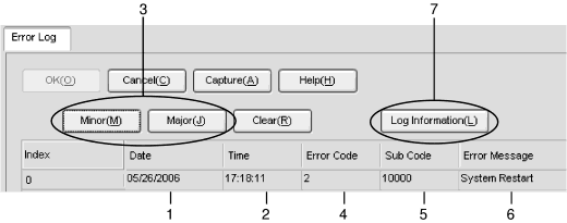
Below is the display format of the error log. For information about how to view the error log using the KX-TDE Maintenance Console, refer to "2.6.8 Utility—Error Log" in the PC Programming Manual.

Example: Maintenance Console

imc4035a.gif
 

Example: Station Message Detail Recording (SMDR)

imc4040a.gif

Description


Item

Description

1
Date
The date of the error detection.
2
Time
The time of the error detection.
3
Level
Minor (MN ALM)
Displays minor errors, which affect only a certain part of system operation.
Major (MJ ALM)
Displays major errors, which affect operation of the whole system, or result in system failure.
4
Error Code
The 3-digit error code assigned by the PBX.
5
Sub Code
The 6-digit sub code of the relevant hardware (X1YYZZ).
X: Shelf type
Physical shelf: " " (blank)
Virtual shelf: "*" (asterisk)
1: Shelf number
YY: Slot number
KX-TDE100 (Physical slot): 00 to 06
(00: IPCMPR Card Slot; 01 to 06: Free Slots)
KX-TDE200 (Physical slot): 00 to 11
(00: IPCMPR Card Slot; 01 to 11: Free Slots)
KX-TDE100/KX-TDE200 (Virtual slot): 01 to 08
(01 to 04: Virtual CO Line Slots; 05 to 08: Virtual Extension Slots)
ZZ: Port number
For optional service cards except OPB3 card:
Port number (01 to 16) will be displayed.
For OPB3 card:
Sub slot number (1 to 3) + port number (1 to 4) will be displayed as follows:
Sub slot 1 of OPB3: 11 to 14
Sub slot 2 of OPB3: 21 to 24
Sub slot 3 of OPB3: 31 to 34
Note
When there is no parameter for slot and port number, YY and ZZ will be displayed as "00".
Example: Sub code for IPCMPR card = " 10000"
6
Error Message
A description of the error.
7
Log Information
Displays probable causes of the errors and their solutions.