1.19 V

1.19.1 Verification Code Entry

Description

An extension user can enter a verification code when calling from his own or any other extension, to change the Toll Restriction (TRS) level (→ 1.17.6 TRS (Toll Restriction)) or to identify the call for accounting and billing purposes. A verification code personal identification number (PIN) is required to use this feature.

Conditions

WARNING
There is a risk that fraudulent telephone calls will be made if a third party discovers a personal identification number (PIN) (verification code PIN or extension PIN) of the PBX. The cost of such calls will be billed to the owner/renter of the PBX. To protect the PBX from this kind of fraudulent use, we strongly recommend:
a) Keeping PINs secret.
b) Selecting complex, random PINs that cannot be easily guessed.
c) Changing PINs regularly.
When a CO line call is made using Verification Code Entry:
the Class of Service of the specified extension is applied (→ 1.3.20 COS (Class of Service))
the Itemized Billing code of the specified extension is applied (→ 1.1.3 ARS (Automatic Route Selection))
asterisk.gif + verification code is recorded on SMDR as the call originator, instead of the extension number of the actual extension used (→ 1.16.3 SMDR (Station Message Detail Recording)).
Verification Code Entry through DISA
This feature is also available through DISA. (→ 1.4.8 DISA (Direct Inward System Access))
Verification Code PIN
A verification code PIN must be assigned for each verification code through system programming or through manager programming.
Verification Code PIN Lock
If the wrong PIN is entered three times, the line will be disconnected. If the wrong PIN is entered a preprogrammed number of times successively, the PIN for the verification code will be locked. Only an extension assigned as the manager can unlock it. In this case, the PIN will be unlocked and cleared.
[Example of Verification Codes and Their Programming]

Location

Code*1

Name*2

PIN*3

COS*4

Itemized Billing Code for ARS*5

0001
1111
Tom Smith
1234
1
2323
0002
2222
John White
9876543210
3
4545
:
:
:
:
:
:
*1:
2.13.3 [6-3] Verification Codelozenge.gifVerification Code
[120] Verification Code
*2:
2.13.3 [6-3] Verification Codelozenge.gifUser Name
[121] Verification Code Name
*3:
2.13.3 [6-3] Verification Codelozenge.gifVerification Code PIN
[122] Verification Code Personal Identification Number (PIN)
*4:
2.13.3 [6-3] Verification Codelozenge.gifCOS Number
[123] Verification Code COS Number
*5
2.13.3 [6-3] Verification Codelozenge.gifItemized Billing Code for ARS

Programming References

PC Programming Manual
2.9.5 [2-3] Timers & CountersMiscellaneouslozenge.gifExtension PIN—Lock Counter
2.9.9 [2-6-1] Numbering Plan—MainFeatureslozenge.gifUser Remote Operation / Walking COS / Verification Code
2.11.1 [4-1-1] Wired Extension—Extension SettingsOption 1lozenge.gifARS Itemized Code
2.11.10 [4-2-1] Portable Station—Extension SettingsOption 1lozenge.gifARS Itemized Code
2.13.3 [6-3] Verification Code
PT Programming Manual
[120] Verification Code
[121] Verification Code Name
[122] Verification Code Personal Identification Number (PIN)
[123] Verification Code COS Number

Feature Manual References

1.1.3 ARS (Automatic Route Selection)
1.3.20 COS (Class of Service)
1.11.1 Manager Features
2.1 Capacity of System Resources

Operating Manual References

1.3.67 Verification Code Entry
3.2.2 Manager Programming

1.19.2 Virtual PS

Description

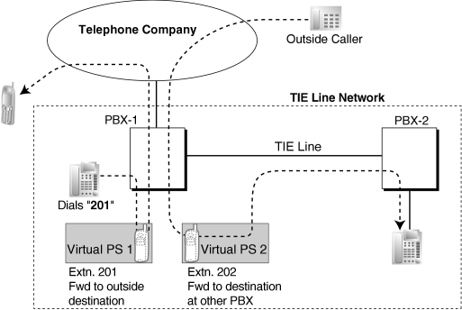
An extension number can be assigned for a portable station (PS) without registering the PS unit itself. This is known as temporary registration. If a forward destination is then assigned for this PS, all calls to that extension number will be forwarded to the assigned destination. Using this setting to forward calls to outside destinations or destinations at another PBX allows those destinations to receive calls as if they were within the PBX. In addition, depending on system programming, the forward destination can use some of the features of the PBX. This can be especially useful for a cellular phone user, who can use his cellular phone as if it were his extension when he is away from his desk.

[Example]

virtualps.gif
The following features can be accessed using this method:

Feature

Description & Reference

Outside Destinations in Incoming Call Distribution Group
A virtual PS allows calls to an Incoming Call Distribution (ICD) Group to be answered by outside destinations or extensions at another PBX.
1.9.4 ICD Group Features—Outside Destinations
Network ICD Group
Using virtual PSs in an ICD Group, up to 4 other PBXs can be called at the same time.
1.13.18 Private Network Features—Network ICD Group
PS Roaming by Network ICD Group
One PS can be registered at up to 4 PBXs. Using virtual PSs in an ICD Group, all 4 PBXs can be called simultaneously to search for the PS.
1.13.19 Private Network Features—PS Roaming by Network ICD Group
Simplified Voice Message
Registering a virtual PS as the first extension of an ICD Group provides the ICD Group with a dedicated message box that is not shared with an actual extension.
1.16.8 SVM (Simplified Voice Message)

Conditions

To use this feature, call forwarding to CO lines must be enabled through COS programming.

Programming References

PC Programming Manual
2.8.44 [1-2] Portable StationPS Registration and De-registration
PT Programming Manual
[690] PS Registration

Feature Manual References

1.6.6 FWD (Call Forwarding)

1.19.3 Voice Mail (VM) Group

Description

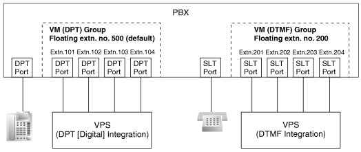
A VPS can be connected to extension ports of the PBX. The extension ports make a group, called a VM group. This group has a floating extension number. The VM group can be the destination for redirected calls and incoming calls. When receiving a call, the VPS can greet the caller offering them the option to leave a message or dial a number to reach the desired party. The VPS can record the message for each extension and leave notification on the corresponding extension, if the called extension is not able to answer calls.
1. VM Group Type

Type

Description

VM (DTMF) Group
A group of SLT ports which use the Voice Mail DTMF Integration features.
A maximum of 2 groups can be assigned.
VM (DPT) Group
A group of DPT ports which use the Voice Mail DPT (Digital) Integration features.
A maximum of 2 KX-TVS/KX-TVP systems can be connected to the PBX.
A maximum of one VM (DPT) group per KX-TVS/KX-TVP can be assigned.
A maximum of 12 ports (24 channels) of the VPS can form each group.

[Example]

imf1270a.gif
VM (DTMF) Group Assignment:
The VPS is connected to the SLT ports of the PBX. These SLT ports, as well as VM (DTMF) Group settings, must be configured to allow DTMF Integration, as shown in the following [Programming Example of Extension Port] and [Programming Example of VM (DTMF) Group].
 
VM (DPT) Group Assignment:
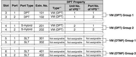
The VPS is connected to the DPT ports of the PBX. These DPT ports, as well as VM (DPT) group settings, must be configured to allow DPT (Digital) Integration, as shown in the following [Programming Example of Extension Port] and [Programming Example of VM (DPT) Group].
 

[Programming Example of Extension Port]

imf1276a.gif
*1:
2.8.21 [1-1] Slot—Port Property - Extension Portlozenge.gifDPT Type—Type
[601] Terminal Device Assignment
*2:
2.8.21 [1-1] Slot—Port Property - Extension Portlozenge.gifDPT Type—VM Unit No.
*3:
2.8.21 [1-1] Slot—Port Property - Extension Portlozenge.gifDPT Type—VM Port No.

[Programming Example of VM (DTMF) Group]

imf1277a.gif
2.10.22 [3-8-2] VM(DTMF) Group—Group Settings
 

[Programming Example of VM (DPT) Group]

imf1278a.gif
*1:
2.10.19 [3-7-2] VM(DPT) Group—Unit Settingslozenge.gifFloating Extension No.
[660] VM Group Floating Extension Number
*2:
2.10.19 [3-7-2] VM(DPT) Group—Unit Settingslozenge.gifGroup Name
2. Incoming Calls to VM Group
When incoming calls are received at the floating extension number of the VM group, calls will hunt starting at the lowest VM port number. In this case, the FWD and DND settings (→ 1.4.10 DND (Do Not Disturb), → 1.6.6 FWD (Call Forwarding)) for each extension port are disregarded.
It is programmable whether the calls queue when all extension ports in the group are busy through system programming. If the queuing is disabled through system programming, the call will be redirected to the destination, assigned on the trunk group which receives the call, by the Intercept Routing feature.

Conditions

It is possible to call an extension (extension port) in a VM group directly. If the calls are routed directly to the extension in the group, it is possible to enable some features (e.g., FWD, Idle Extension Hunting) on the extension in the group.
The Voice Mail DTMF/DPT (Digital) Integration (e.g., command transmit) is also available on the extension.
One-touch Voice Mail Feature Access
It is possible to assign a One-touch Dialing button for direct access to a Voice Mail feature. (→ 1.12.4 One-touch Dialing) For example, to access a mailbox (mailbox number 123) of the VPS (extension number 165) directly, assign "165#6123" to a One-touch Dialing button. When pressing this button, the outgoing message (OGM) of the mailbox will be heard.
All ports in a VM (DPT) group must be connected to a single DHLC or DLC card.

Programming References

PC Programming Manual
2.8.21 [1-1] Slot—Port Property - Extension Port
    → lozenge.gifDPT Type—Type
    → lozenge.gifDPT Type—VM Unit No.
    → lozenge.gifDPT Type—VM Port No.
2.10.18 [3-7-1] VM(DPT) Group—System Settings
2.10.19 [3-7-2] VM(DPT) Group—Unit Settings
2.10.21 [3-8-1] VM(DTMF) Group—System Settings
2.10.22 [3-8-2] VM(DTMF) Group—Group Settings
PT Programming Manual
[601] Terminal Device Assignment
[660] VM Group Floating Extension Number

Feature Manual References

1.19.4 Voice Mail DPT (Digital) Integration
1.19.5 Voice Mail DTMF Integration
2.1 Capacity of System Resources

1.19.4 Voice Mail DPT (Digital) Integration

Description

A Panasonic VPS that supports DPT (Digital) Integration (e.g., the KX-TVP200) can be connected to this PBX in a tightly integrated fashion.
DPT (Digital) Integration features can be used when the VPS is connected through DPT ports of the PBX.

Feature Explanation

1. Automatic Configuration—Quick Setup
The PBX informs the VPS of its extension numbers and the floating extension numbers of the incoming call distribution groups so that the VPS can create mailboxes with this data automatically.
2. FWD to a Mailbox of the VPS
If an extension user sets FWD to the VPS, incoming calls are forwarded to the VPS. (→ 1.6.6 FWD (Call Forwarding)) The PBX sends a mailbox number of the forwarding extension to the VPS. Therefore the caller can leave a message in the mailbox of the extension without knowing the mailbox number.
3. Intercept Routing to a Mailbox of the VPS
If an extension user sets Intercept Routing to the VPS, the intercepted CO line calls will be redirected to the VPS. (→ 1.9.11 Intercept Routing) If the "Intercept to Mailbox" setting is enabled through system programming, the PBX sends the mailbox number of the intercepted extension to the VPS. Therefore the caller can leave a message in the mailbox of the extension without knowing the mailbox number.
2.10.18 [3-7-1] VM(DPT) Group—System Settingslozenge.gifIntercept to Mailbox
4. Transferring to a Mailbox of the VPS
An extension user can transfer a call to a mailbox of the VPS so that the caller can leave a message in the mailbox of the desired extension. (→ 1.3.9 Call Transfer) The extension user should use the Voice Mail (VM) Transfer button, when transferring a call to the mailbox of the VPS. When the extension user presses this button and enters the desired extension number, the PBX will transfer the call to the VM group and dial the mailbox number of the desired extension number with the required command (after the VPS answers the call). Therefore the caller can leave a message without knowing the mailbox number.
5. Transfer Recall to a Mailbox of the VPS
If a call is transferred to an extension via the Automated Attendant (AA) service of the VPS and the call is not answered within a preprogrammed Transfer Recall time, the PBX sends the mailbox number of the transfer destination extension to the VPS. Therefore the caller can leave a message in the mailbox of the extension without knowing the mailbox number. The "Transfer Recall to Mailbox" setting should be enabled through system programming to use this feature.
2.9.5 [2-3] Timers & CountersDial / IRNA / Recall / Tonelozenge.gifRecall—Transfer Recall
2.10.18 [3-7-1] VM(DPT) Group—System Settingslozenge.gifTransfer Recall to Mailbox
[201] Transfer Recall Time
6. Listening to a Recorded Message (Direct Mailbox Access)
If the VPS receives a message, the VPS will set the Message Waiting feature (e.g., turning on the Message button light, and showing the number of messages waiting on the display of a 6-line display PT) on the corresponding telephone as notification. (→ 1.11.3 Message Waiting) Thereby, the VPS notifies the extension user that there is a message waiting in his mailbox. When the Message button light turns on, pressing the button allows the extension user to play back the messages stored in his mailbox without dialing such as a mailbox.
When the extension user dials an extension number of the VM (DPT) extension port or the floating extension number of the VM (DPT) group from his extension, he can listen to the messages stored in his mailbox without dialing his mailbox number (Direct Mailbox Access). It is possible to disable this feature by COS programming on the VPS.
7. VPS CO Line Service & Automatic Time Mode Notification for Incoming Call*
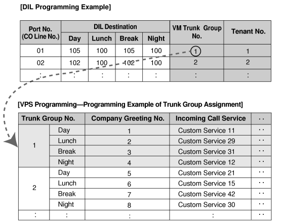
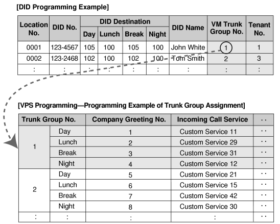
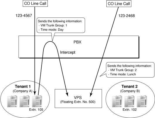
Multiple tenants can share a single VPS; each tenant does not require a dedicated VPS port. If the destination of the incoming CO line call is a VM (DPT) group, the PBX sends the VM trunk group number and time mode (day/lunch/break/night) of the tenant (→ 1.17.5 Time Service) assigned for the call to the VPS. Therefore the VPS can send the assigned message (company greeting) to the caller. Corresponding VM trunk group number and tenant number are determined by the setting of the incoming CO line call as follows:
a) DIL/TIE: the setting of each CO line port (→ 1.4.7 DIL (Direct In Line), 1.13.15 PRIVATE NETWORK FEATURES)
2.17.2 [10-2] DIL Table & Port SettingsDIL
   → lozenge.gifTenant Number
   → lozenge.gifVM Trunk Group No.
b) DID: the setting of each location number for DID (→ 1.4.6 DID (Direct Inward Dialing))
2.17.3 [10-3] DID Table
   → lozenge.gifTenant Number
   → lozenge.gifVM Trunk Group No.
[Example]
For DIL Calls:
Each location number can have its VM trunk group number (message number) and tenant number.
imf1905a-1.gif
Explanation:
A CO line call handled by DIL distribution reaches a VM (DPT) group directly or by the Intercept Routing feature. According to the [DIL Programming Example] and [VPS Programming—Programming Example of Trunk Group Assignment], a caller will hear a corresponding company greeting of the VPS.
Time mode (day/lunch/break/night) of the preprogrammed tenant is applied to the DIL destination and company greeting number.
[Example]
For DID Calls:
Each location number can have its VM trunk group number (message number) and tenant number.
imf1905a.gif
Explanation:
A DID call reaches a VM (DPT) group directly or by the Intercept Routing feature. According to the [DID Programming Example] and [VPS Programming—Programming Example of Trunk Group Assignment], a caller will hear a corresponding company greeting of the VPS.
Time mode (day/lunch/break/night) of the preprogrammed tenant is applied to the DID destination and company greeting number.
imf1906a.gif
 
8. Caller's Identification Notification to the VPS
When receiving a CO line call, the PBX sends the caller's identification number/name to the VPS.
9. DID Number Notification to the VPS
When receiving a CO line call with a DID number, the PBX sends the DID number to the VPS. The number will be sent to the VPS even if the call reaches the VPS after redirection by, for example, the Intercept Routing feature.
10. Status Notification to the VPS
After the call is redirected by the VPS, the PBX sends the status of the redirected extension (e.g., busy) to the VPS.
11. Paging by the VPS
The VPS can perform the Paging feature using the recorded message. (→ 1.13.1 Paging)
12. Live Call Screening (LCS)
A PT or PS user can monitor his own mailbox while a caller is leaving a message and, if desired, answer the call by pressing the LCS button. When the caller is leaving a message in the mailbox, monitoring can be carried out in two ways: each PT user can choose which through personal programming (Live Call Screening Mode Set). PS users cannot choose the way: only Private mode is available for them.
Hands-free mode: The user can monitor the call automatically through the built-in speaker.
Private mode: The user will hear a warning tone. To monitor the call, the user goes off-hook with the handset, MONITOR button, or SP-PHONE button. However, PS users cannot monitor the call with the speakerphone.
2.11.1 [4-1-1] Wired Extension—Extension SettingsOption 4lozenge.gifLCS Answer Mode
13. Two-way Recording into the VPS
A PT user can record a conversation into his own mailbox or another mailbox, while talking on the phone.
The Two-way Record button is used to record into one's own mailbox. The Two-way Transfer button is used to record into someone else's mailbox.
Note
Before recording a Two-way telephone conversation, you should inform the other party that the conversation will be recorded.
14. VPS Data Control by the PBX*
The date and time settings of the VPS are controlled by the PBX.
15. Remote FWD Setting by the VM*
Extension FWD settings can be programmed using the VPS.
*:
This feature may not be supported depending on the software version of the VPS.

Conditions

[General]

When programming a KX-TVA series VPS, if there is no option to connect to a KX-TDE100/KX-TDE200 PBX, select the KX-TDA100/KX-TDA200 PBX.
Voice Mail (VM) Transfer Button
A flexible button can be customized as the Voice Mail (VM) Transfer button with the floating extension number of the VM group as the parameter.

[Live Call Screening (LCS)]

This feature is not available for SIP extensions.
If an SLT is connected in parallel to a PT, and if LCS is activated for the PT in Private mode, both the PT and SLT can be used to monitor calls while in idle status. The SLT will ring to indicate a message is being recorded. The call can be monitored with the SLT by going off-hook. To intercept the call, press Flash/Recall button or flash the hookswitch. (→ 1.13.2 Paralleled Telephone)
LCS Button
A flexible button can be customized as the LCS button.
Extension Personal Identification Number (PIN)
To prevent unauthorized monitoring, it is recommended the LCS user assign an extension PIN. This PIN will be required when setting LCS. (→ 1.5.6 Extension PIN (Personal Identification Number)) If the user forgets the PIN, it can be cleared by an extension assigned as the manager.
Each extension can be programmed to either end recording or continue recording the conversation after the call is intercepted, through personal programming (LCS Mode Set [After Answering]).
2.11.1 [4-1-1] Wired Extension—Extension SettingsOption 4lozenge.gifLCS Recording Mode
2.11.10 [4-2-1] Portable Station—Extension SettingsOption 4lozenge.gifLCS Recording Mode
To use the LCS feature on a PS in Wireless XDP Parallel Mode, LCS can only be turned on or off from the wired telephone. In Wireless XDP Parallel Mode, setting LCS on/off from the PS has no effect. (→ 1.20.5 Wireless XDP Parallel Mode)

[Two-way Recording into the VPS]

Two-way Record/Two-way Transfer Button
A flexible button can be customized as the Two-way Record or the Two-way Transfer button. An extension number can be assigned to the Two-way Transfer button so that it can be used as a one-touch record button for the mailbox of the specified extension. (One-touch Two-way Transfer Button).
When all of the VPS ports are busy:
a) Pressing the Two-way Record button sends a warning tone
b) Pressing the Two-way Transfer button followed by an extension number sends a warning tone.

[Transferring to a Mailbox of the VPS]

When transferring a CO line call to a mailbox of the VPS, users should use the VM Transfer button.
If using a standard Transfer button, users must dial "#6" after accessing the VPS, and confirm that the desired mailbox has been reached, before going on hook to complete the transfer.

Programming References

PC Programming Manual
2.9.5 [2-3] Timers & CountersDial / IRNA / Recall / Tonelozenge.gifRecall—Transfer Recall
2.10.18 [3-7-1] VM(DPT) Group—System Settings
2.10.19 [3-7-2] VM(DPT) Group—Unit Settings
2.11.1 [4-1-1] Wired Extension—Extension SettingsOption 4
    → lozenge.gifLCS Recording Mode
    → lozenge.gifLCS Answer Mode
2.11.5 [4-1-4] Wired Extension—Flexible Button
    → lozenge.gifType
    → lozenge.gifExt. No. / Floating Ext. No. (for Two-way Record)
    → lozenge.gifExt. No. / Floating Ext. No. (for Two-way Transfer)
    → lozenge.gifExt. No. / Floating Ext. No. (for Voice Mail Transfer)
    → lozenge.gifExtension No. of Mailbox (for Two-way Transfer)
2.11.10 [4-2-1] Portable Station—Extension SettingsOption 4lozenge.gifLCS Recording Mode
2.11.13 [4-2-3] Portable Station—Flexible Button
    → lozenge.gifType
    → lozenge.gifExt. No. / Floating Ext. No. (for Two-way Record)
    → lozenge.gifExt. No. / Floating Ext. No. (for Two-way Transfer)
    → lozenge.gifExt. No. / Floating Ext. No. (for Voice Mail Transfer)
    → lozenge.gifExt No. of Mailbox (for Two-way Transfer)
2.11.17 [4-3] DSS Console
    → lozenge.gifType
    → lozenge.gifExt. No. / Floating Ext. No. (for Two-way Record)
    → lozenge.gifExt. No. / Floating Ext. No. (for Two-way Transfer)
    → lozenge.gifExt. No. / Floating Ext. No. (for Voice Mail Transfer)
    → lozenge.gifExt No. of Mailbox (for Two-way Transfer)
2.12.1 [5-1] Doorphonelozenge.gifVM Trunk Group Number
2.17.2 [10-2] DIL Table & Port SettingsDIL
    → lozenge.gifTenant Number
    → lozenge.gifVM Trunk Group No.
2.17.3 [10-3] DID Table
    → lozenge.gifTenant Number
    → lozenge.gifVM Trunk Group No.
PT Programming Manual
[201] Transfer Recall Time

Feature Manual References

1.6.3 Flexible Buttons
1.6.4 Flexible Numbering/Fixed Numbering
1.19.3 Voice Mail (VM) Group

Operating Manual References

1.3.69 Voice Mail Features—LCS (Live Call Screening)
1.3.70 Voice Mail Features—Two-way Record
1.3.71 Voice Mail Features—Voice Mail Integration
3.1.2 Personal Programming
3.2.2 Manager Programming

1.19.5 Voice Mail DTMF Integration

Description

The PBX and the VPS connected to the PBX can transmit commands using DTMF signals to each other. The PBX sends preprogrammed commands using DTMF to the VPS automatically to change the answering service between Voice Mail (VM) service mode and Automated Attendant (AA) service mode or to inform the extension status (e.g., busy). The VPS sends the commands to the PBX like an SLT.
The following answering services and features are available:
1. Voice Mail (VM) Service Mode
When a caller reaches the VPS, the VPS greets and guides the caller to leave a voice message for a specified mailbox.
[Example]
The VPS sends the message to the caller, "Thank you for calling Panasonic. Please enter the mailbox number of the person you wish to leave your message for."
          ↓
The caller dials the mailbox number. Then, the dialed number is sent to the VPS via the PBX.
          ↓
The VPS sends the personal greeting to the caller, "You have reached Mike's voice mail. I am sorry I cannot take your call right now. Please leave a message and I will call you back."
          ↓
The caller leaves a message.
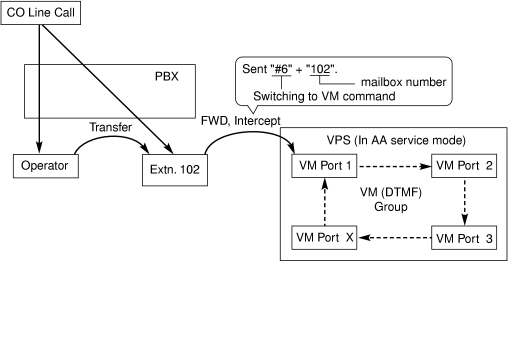
If the call reroutes to the floating extension number of the VM (DTMF) Group or the extension in the VM (DTMF) group by such as the FWD feature, when the VPS answers the call, the PBX will dial the mailbox number of the corresponding group or extension and any other digits required to the VPS automatically using the caller-dialed number (Follow on ID). In this case, the caller can reach a mailbox without knowing the mailbox number.
[Available Features for Follow on ID]
a) FWD to a Mailbox
b) Intercept Routing to a Mailbox
c) Call Transfer to a Mailbox
d) Listening to a Message in a Mailbox
2. Automated Attendant (AA) Service Mode
The VPS greets and guides the caller to the desired extension directly without operator assistance.
3. VM → AA Service, AA → VM Service
It is possible to switch the service mode assigned on the VPS port, from the VM service to AA service or vice versa.

System Explanation

1. Service Mode Assignment
Assign the service mode, VM service or AA service, to the VM (DTMF) group to correspond with the assignment of the VPS.
2.10.22 [3-8-2] VM(DTMF) Group—Group Settingslozenge.gifType
2. DTMF Command Assignment
Assign the DTMF command to suit the VPS settings.
2.10.21 [3-8-1] VM(DTMF) Group—System Settings
    → lozenge.gifVM DTMF Command—Recording Message
    → lozenge.gifVM DTMF Command—Listening Message
    → lozenge.gifVM DTMF Command—Switching to AA
    → lozenge.gifVM DTMF Command—Switching to VM

Command (Default)

Switching to VM
#6
Switching to AA
#8
Recording message
H
Listening message
asterisk.gifH
Note
H = Mailbox Number
3. VM Service
a) FWD to a Mailbox of the VPS
The PBX sends a mailbox number of the corresponding extension to the VPS when a call is forwarded from an extension to the VPS. Therefore the caller can leave a message for the called extension without knowing the mailbox number.

[FWD to the VPS Sequence Selection]
If an extension user sets FWD to the VPS, any incoming call will be forwarded to the VPS.
It is also possible to send the AA command, even in the VM service mode, when calls are forwarded so that the caller can be directed to an extension rather than a mailbox. This can be performed by selecting "AA" through system programming.
2.10.21 [3-8-1] VM(DTMF) Group—System Settingslozenge.gifOthers—FWD to the VPS Sequence

Parameter

Transmitted Command

In AA Service Mode

In VM Service Mode

Answer by Mailbox (Default)
Switching to VM command + Recording message command (#6 + H [H = Mailbox No.])
Recording message command (H [H = Mailbox No.])
AA
Switching to AA command (#8)
None
(DTMF commands are not sent. Work with default of the VPS.)
b) Intercept Routing to a Mailbox of the VPS
The PBX sends a mailbox number of the corresponding extension to the VPS when a CO line call is intercepted from an extension to the VPS. Therefore the caller can leave a message for the called extension without knowing the mailbox number.

[Intercept Routing to the VPS Sequence Selection]
If an extension user sets Intercept Routing to the VPS, the intercepted CO line calls will be redirected to the VPS.
It is also possible to send the AA command, even in the VM service mode, when calls are intercepted so that the caller can be directed to an extension rather than a mailbox. This can be performed by selecting "AA" through system programming.
2.10.21 [3-8-1] VM(DTMF) Group—System Settingslozenge.gifOthers—Intercept Routing to the VPS Sequence

Parameter

Transmitted Command

In AA Service Mode

In VM Service Mode

Answer by Mailbox
Switching to VM command + Recording message command (#6 + H [H = Mailbox No.])
Recording message command (H [H = Mailbox No.])
AA
Switching to AA command (#8)
None (Default)
(DTMF commands are not sent. Work with default of the VPS.)

[Example of a) & b)]

imf1290a.gif
c) Transferring to a Mailbox of the VPS
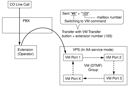
An extension user can transfer a call to a mailbox of the VPS so that the caller can leave a message in the mailbox of the desired extension. (→ 1.3.9 Call Transfer) The extension user should use the Voice Mail (VM) Transfer button, when transferring a call to the mailbox of the VPS. When the extension user presses this button and enters the desired extension number, the PBX will transfer the call to the VM group and dial the mailbox number of the desired extension with the required command (after the VPS answers the call). Therefore the caller can leave a message without knowing the mailbox number.
2.11.5 [4-1-4] Wired Extension—Flexible Button
    → lozenge.gifType
    → lozenge.gifExt. No. / Floating Ext. No. (for Voice Mail Transfer)
2.11.13 [4-2-3] Portable Station—Flexible Button
    → lozenge.gifType
    → lozenge.gifExt. No. / Floating Ext. No. (for Voice Mail Transfer)
2.11.17 [4-3] DSS Console
    → lozenge.gifType
    → lozenge.gifExt. No. / Floating Ext. No. (for Voice Mail Transfer)
[Performance of Pressing the VM Transfer Button and Entering an Extension Number]

Transmitted Command

In AA Service Mode

In VM Service Mode

Switching to VM command + Recording message command (#6 + H [H = Mailbox No.])
Recording message command (H [H = Mailbox No.])

[Example]

imf1300a.gif
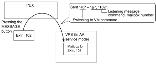
d) Listening to a Recorded Message
If the VPS receives a message, the VPS will set the Message Waiting feature on the corresponding telephone to notify the extension user that there is a message waiting in his mailbox. The Message button light of the extension will turn on (→ 1.11.3 Message Waiting), thereby notifying the extension user that there is a message waiting in his mailbox. When the Message button light turns on, pressing the button allows the extension user to play back the messages stored in his mailbox without dialing such as a mailbox number. It is programmable whether the PBX or the VPS cancels the Message Waiting feature (e.g., turning off the Message button light).
2.10.21 [3-8-1] VM(DTMF) Group—System Settingslozenge.gifOthers—Message Waiting Lamp Control

When the PBX is selected, the Message Waiting feature is canceled after the extension user has accessed the VPS. When the VPS is selected, the Message Waiting feature is canceled after the extension user has listened to messages stored in his mailbox.
[Performance of Pressing the MESSAGE Button]

Transmitted Command

In AA Service Mode

In VM Service Mode

Switching to VM command + Listening message command
(#6 + asterisk.gifH [H = Mailbox No.])
Listening message command (asterisk.gifH [H = Mailbox No.])

[Example]

imf1920a.gif
 
4. AA Service
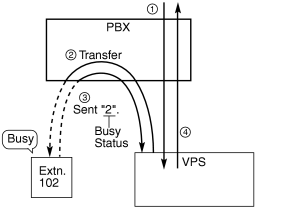
If the VPS transfers the call using the AA service, the PBX will inform the VPS of the status of the called destination with the preprogrammed DTMF status signal so that the VPS can confirm the status of the extension without listening to the system tones (e.g., ringback tone).
Assign the DTMF status signal to suit the VPS settings.

[DTMF Status Signals and Conditions]

Status

Condition

Default Command

RBT (ringback tone)
The PBX is ringing the corresponding extension.
1
BT (busy tone)
The called extension is busy.
2
ROT (reorder tone)
The dialed number is invalid.
3
DND (DND tone)
The called extension has set DND. (→ 1.4.10 DND (Do Not Disturb))
4
Answer
The called extension has answered the call.
5
FWD VM RBT (FWD to Voice Mail ringback tone)
The called extension has set FWD to VPS and the PBX is calling another port of the VPS.
6
FWD VM BT (FWD to Voice Mail busy tone)
The called extension has set FWD to VPS and all ports of the VPS are busy.
7
FWD EXT RBT (FWD to extension ringback tone)
The PBX is calling an extension other than the one dialed. FWD or Idle Extension Hunting (→ 1.9.9 Idle Extension Hunting) may be assigned by the called extension.
8
Confirm (confirmation tone)
The PBX receives confirmation that the feature has been successfully set or canceled (e.g., Message Waiting) on the extension.
9
Disconnect
The caller has hung up.
#9
2.10.21 [3-8-1] VM(DTMF) Group—System Settings
    → lozenge.gifVM DTMF Status Signal—Ringback Tone
    → lozenge.gifVM DTMF Status Signal—Busy Tone
    → lozenge.gifVM DTMF Status Signal—Reorder Tone
    → lozenge.gifVM DTMF Status Signal—DND Tone
    → lozenge.gifVM DTMF Status Signal—Answer
    → lozenge.gifVM DTMF Status Signal—Confirm
    → lozenge.gifVM DTMF Status Signal—Disconnect
    → lozenge.gifVM DTMF Status Signal—FWD to VM Ringback Tone
    → lozenge.gifVM DTMF Status Signal—FWD to VM Busy Tone
    → lozenge.gifVM DTMF Status Signal—FWD to Extension Ringback Tone

[Example]

imf1950a.gif
circle1.gif
An incoming call reaches the VPS. The VPS greets the caller: "Thank you for calling Panasonic. If you know the extension number of the person you wish… ".
circle2.gif
The caller dials the extension number (extn. 102). The VPS will transfer the call to the extension via the PBX.
circle3.gif
If the extension is not available, the PBX sends DTMF status signal of the extension (busy status) to the VPS.
circle4.gif
The VPS receives the DTMF status signal and send the appropriate message to the caller: "Sorry. The extension is busy. Would you like to leave a message… ".

Conditions

Voice Mail (VM) Transfer Button
A flexible button can be customized as the Voice Mail (VM) Transfer button with the floating extension number of the VM group as the parameter.
It is possible to assign the time period between when the VPS answers the call and the PBX sends the Follow on ID to the VPS.
2.10.21 [3-8-1] VM(DTMF) Group—System Settingslozenge.gifTiming—Waiting Time before Sending Follow on ID
It is possible to assign the time period between when the VPS transfers the call using the AA service to the PBX and the PBX sends the DTMF status signal to the VPS.
2.10.21 [3-8-1] VM(DTMF) Group—System Settingslozenge.gifTiming—DTMF Length for VM
It is possible to select whether the mailbox number is the same as the extension number, or the mailbox number is programmable for each extension number and incoming call distribution group (Mailbox Access ID).
2.10.12 [3-5-1] Incoming Call Distribution Group—Group SettingsMiscellaneouslozenge.gifProgrammed Mailbox No.
2.11.1 [4-1-1] Wired Extension—Extension SettingsOption 1lozenge.gifProgrammed Mailbox No.
2.11.10 [4-2-1] Portable Station—Extension SettingsOption 1lozenge.gifProgrammed Mailbox No.
The Inter-digit time for the DTMF command and for DTMF status signal is programmable.
2.10.21 [3-8-1] VM(DTMF) Group—System Settings
   → lozenge.gifTiming—Inter-digit Time
   → lozenge.gifTiming—Waiting Time before Sending VM DTMF Status Signal
Data Line Security is set automatically on the extensions in the VM (DTMF) group to achieve proper recording. (→ 1.4.1 Data Line Security)

Programming References

PC Programming Manual
2.9.5 [2-3] Timers & CountersMiscellaneouslozenge.gifVoice Mail (Caller from VM to CO)—On-hook Wait Time
2.10.12 [3-5-1] Incoming Call Distribution Group—Group SettingsMiscellaneouslozenge.gifProgrammed Mailbox No.
2.10.21 [3-8-1] VM(DTMF) Group—System Settings
2.10.22 [3-8-2] VM(DTMF) Group—Group Settings
2.11.1 [4-1-1] Wired Extension—Extension SettingsOption 1lozenge.gifProgrammed Mailbox No.
2.11.5 [4-1-4] Wired Extension—Flexible Button
    → lozenge.gifType
    → lozenge.gifExt. No. / Floating Ext. No. (for Voice Mail Transfer)
2.11.10 [4-2-1] Portable Station—Extension SettingsOption 1lozenge.gifProgrammed Mailbox No.
2.11.13 [4-2-3] Portable Station—Flexible Button
    → lozenge.gifType
    → lozenge.gifExt. No. / Floating Ext. No. (for Voice Mail Transfer)
2.11.17 [4-3] DSS Console
    → lozenge.gifType
    → lozenge.gifExt. No. / Floating Ext. No. (for Voice Mail Transfer)
PT Programming Manual
None

Feature Manual References

1.3.9 Call Transfer
1.6.3 Flexible Buttons
1.6.6 FWD (Call Forwarding)
1.9.11 Intercept Routing
1.19.3 Voice Mail (VM) Group

Operating Manual References

1.3.71 Voice Mail Features—Voice Mail Integration