1.16 S

1.16.1 Self Labeling (KX-NT366 only)

Description

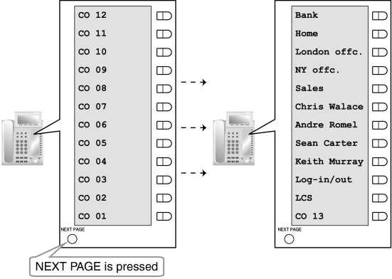
The KX-NT366 IP-PT features 12 flexible buttons, with an LCD screen next to the buttons. Each item can be named on the LCD screen through personal/system programming to reflect the function of its corresponding flexible button. Additionally, the flexible buttons can be organized into 4 "pages", allowing you to assign a total of 48 items to the 12 flexible buttons. You can toggle between pages by pressing the NEXT PAGE key, as follows:
Selflabel.gif

Conditions

Up to 12 characters can be assigned to the LCD of each flexible button through personal/system programming.
When an incoming CO line call is answered or a CO line is seized, the corresponding CO button will turn green and the LCD display will switch to the page that the corresponding CO button is registered in.

Programming References

PC Programming Manual
2.11.5 [4-1-4] Wired Extension—Flexible Buttonlozenge.gifLabel Name
PT Programming Manual
None

Feature Manual References

1.6.3 Flexible Buttons

Operating Manual References

1.3.60 Self Labeling (KX-NT366 only)

1.16.2 SIP (Session Initiation Protocol) Extension

Description

This PBX supports the connection of SIP supported IP telephones (hardphones and softphones). SIP extensions make and receive calls using Internet Protocol (IP).
SIP extensions support the following features:
Account Code Entry (→ 1.1.2 Account Code Entry)
Automatic Route Selection (ARS) (→ 1.1.3 ARS (Automatic Route Selection))
Call Forwarding (FWD)*1 (→ 1.6.6 FWD (Call Forwarding))
Call Hold*2 (→ 1.3.3 Call Hold)
Call Transfer with Announcement (→ 1.3.9 Call Transfer)
Conference*3 (→ 1.3.17 Conference)
Direct Inward System Access (DISA) (→ 1.4.8 DISA (Direct Inward System Access))
Doorphone Call (→ 1.4.12 Doorphone Call)
Emergency Call (→ 1.5.2 Emergency Call)
Idle Line Access (→ 1.3.15 CO Line Access)
Operator Call (→ 1.12.5 Operator Features)
Personal Speed Dialing*1 (→ 1.16.6 Speed Dialing, Personal)
Quick Dialing (→ 1.14.1 Quick Dialing)
S-CO Line Access (→ 1.3.15 CO Line Access)
System Speed Dialing*1 (→ 1.16.7 Speed Dialing, System)
TIE Line Call (→ 1.13.15 PRIVATE NETWORK FEATURES)
Trunk Group Access (→ 1.3.15 CO Line Access)
Verification Code Entry (→ 1.19.1 Verification Code Entry)
*1:
Assigned though system programming only.
*2:
Feature number is not supported.
*3:
As a member only (not as an originator).

Conditions

This PBX supports SIP devices that use RFC 3261, 3264, 3310, 2327, or 4028.
Some SIP phones may not be compatible with this PBX.
Before a SIP extension can be used with the PBX, the IP address of the IPCMPR card, password, and extension number must be assigned on the SIP extension and on the PBX.
For details on how to register, refer to the Information on IP Networking Guide.
When registering the SIP extension, the user ID must be the extension number of the SIP extension.
When a SIP extension uses the Call Hold feature, the target call is put on Consultation Hold.

Installation Manual References

3.4.1 Virtual Cards

Programming References

PC Programming Manual
2.8.17 [1-1] Slot—Card Property - Virtual SIP Extension
2.8.18 [1-1] Slot—Port Property - Virtual SIP Extension Port
2.8.19 [1-1] Slot—Port Property - Virtual SIP Extension Port—Connection Command
PT Programming Manual
None

1.16.3 SMDR (Station Message Detail Recording)

Description

Automatically logs detailed information for each extension.
1. SMDR Output Port
The following output methods can be selected through system programming:
2.18.1 [11-1] MainSMDRlozenge.gifSMDR Format—Port

Output Method

Description

Serial Interface (RS-232C) port
SMDR information is sent to a connected PC, printer, etc.
Telnet compatible terminal emulator
SMDR information is sent to a Telnet compatible terminal emulator via LAN.
2. SMDR Output Data
The following data can be recorded and sent to the SMDR output port:
a) CO line call information (incoming/outgoing)
b) Intercom call information (outgoing)
c) Log-in/Log-out information
d) PBX error log (→ 1.10.4 Local Alarm Information)
e) Hospitality feature information (→ 1.8.4 HOSPITALITY FEATURES)
f) Printing Message information (→ 1.13.13 Printing Message)
Memory for SMDR: A specified number of records (data) can be remembered by the PBX. When memory is full, the oldest data is overwritten by new data.
3. SMDR Format Type and Contents
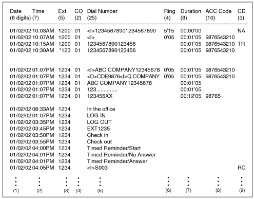
The following three types of output format can be selected through system programming:

Pattern A: 80-column text without call charge information

imf1380a.gif

Pattern B: 80-column text with call charge information

imf1385a.gif

120-column text

imf1390a.gif
[Explanation]
The following table explains the types of data logged by SMDR. Each description below refers to data indicated above by the numbers in the parentheses.

Number in the Pattern

Data

Description

(1)
Date
Shows the date of the call.
(2)
Time
Shows the end time of a call as hour/minute/AM or PM.
(3)
Ext (Extension)
Shows the extension number, floating extension number, etc., which was engaged in the call.
Also shows the following codes:
Dxxx: Outgoing CO line call from a doorphone (xxx=doorphone number) (→ 1.4.12 Doorphone Call)
Txxx: Outgoing CO line call made via TIE line service (xxx=trunk group number)
*xxx: Verified call (xxx=verification code) (→ 1.19.1 Verification Code Entry)
(4)
CO
Shows the CO line number used for the call.
For patterns A and B, "00" will be shown for CO line numbers over hundred.
(5)
Dial Number
[CO Line Call]
Outgoing CO Line Call
Shows the dialed telephone number.
Digits shown are as follows:
0 through 9,Asteriskb.gif, #
P: Pause
F: External Feature Access (EFA) signal
=: Host PBX Access code (→ 1.8.5 Host PBX Access Code (Access Code to the Telephone Company from a Host PBX))
. (dot): Secret dialing

–: Transferred call
If the transfer destination extension enters additional digits, those digits will be added after "–".

Incoming CO Line Call
Shows <I> + the caller's identification name/number.
It is also possible to show the DID call information. In this case, <D> + DID name/number is added before <I> .
[Outgoing Intercom Call]
Shows the dialed extension number followed by "EXT".
[Log-in/Log-out]
Shows the Log-in or Log-out status.
[Check-in/Check-out]
Shows the check-in or check-out status. (→ 1.15.3 Room Status Control)
[Timed Reminder]
Shows the status of a timed reminder, either "Start", "No Answer", or "Answer". (→ 1.17.4 Timed Reminder)
[Printing Message]
Shows the selected message. (→ 1.13.13 Printing Message)
[Sensor Call]
Shows calls from an external sensor as follows:
<I> S + sensor number. (→ 1.5.9 External Sensor)
(6)
Ring
Shows the ring duration before the call was answered in minutes/seconds.
(7)
Duration
Shows the duration of the CO line call in hours/minutes/seconds.
(8)
Acc Code (Account Code)
Shows the account code appended to the call. (→ 1.1.2 Account Code Entry)
(9)
CD (Condition Code)
Shows other call information using the following codes:

TR: Transfer
FW: Call Forwarding (FWD) to CO line
D0: Call using Direct Inward System Access (DISA) or TIE line service
RM: Remote maintenance (modem) (→ 1.13.6 PC Programming)
NA: Not answered call
RC: Received call
AN: Answered call
VR: Received call with Call Waiting Caller ID (Visual Caller ID)
VA: Answered call with Call Waiting Caller ID (Visual Caller ID)
(10)
Cost
Shows the call charge. This is not available if your telephone company does not provide a call charge reporting service.
 
The following data can be controlled through system programming to adjust whether (or how) they are printed or displayed by SMDR
[Programmable Items]

Item

Description

Outgoing CO line call
Controls whether outgoing CO line calls are shown. This setting is common throughout the PBX. COS programming is also required.
2.18.1 [11-1] MainSMDRlozenge.gifPrint Information—Outgoing Call
[804] SMDR Outgoing Call Printing
Incoming CO line call
Controls whether incoming CO line calls are shown.
2.18.1 [11-1] MainSMDRlozenge.gifPrint Information—Incoming Call
[805] SMDR Incoming Call Printing
Outgoing intercom call
Controls whether outgoing intercom calls are recorded.
2.18.1 [11-1] MainSMDRlozenge.gifPrint Information—Intercom Call
Log-in/Log-out status
Controls whether the Log-in/Log-out status of extensions is recorded.
2.18.1 [11-1] MainSMDRlozenge.gifPrint Information—Log-in / Log-out
ARS dial
Controls whether the user-dialed number or the ARS-modified number is shown.
The Host PBX Access code ("=" followed by the access code) can be shown (as supplementary information) only when the modified number is selected in this setting. (→ 1.1.3 ARS (Automatic Route Selection))
2.18.1 [11-1] MainSMDR Optionslozenge.gifOption—ARS Dial
Caller's identification
Controls whether the caller's identification number, name, number and name, or nothing is shown. If "none" is selected, <I> will not be shown.
2.18.1 [11-1] MainSMDR Optionslozenge.gifOption—Caller ID Number & Name
DID number
Controls whether the DID numbers, names, numbers and names, or nothing is shown. If "none" is selected, <D> will not be shown.
2.18.1 [11-1] MainSMDR Optionslozenge.gifOption—DID Number & Name
Secret dialing
Controls the display of secret dialing, when ARS dial above, is set to show ARS-modified numbers. If enabled, numbers dialed secretly will be shown as dots.
If ARS dial is set to show the user-dialed numbers, secretly dialed numbers are always shown as dots in SMDR, regardless of this setting.
2.18.1 [11-1] MainSMDR Optionslozenge.gifOption—Secret Dial
Date order
Controls the date format (MM-DD-YY, DD-MM-YY, YY-MM-DD, YY-DD-MM)
2.18.1 [11-1] MainSMDRlozenge.gifSMDR Format—Date Format
Received call
Controls whether the time of receiving an incoming CO line call is shown.
2.18.1 [11-1] MainSMDR Optionslozenge.gifOption—Condition Code "RC/VR"
Answered call
Controls whether the time of answering an incoming CO line call is shown.
2.18.1 [11-1] MainSMDR Optionslozenge.gifOption—Condition Code "AN/VA"
Room status
Controls whether room status changes are shown.
2.13.2 [6-2] HotelMainlozenge.gifSMDR for External Hotel Application 1—Room Status Control
Timed Reminder call
Controls whether Timed Reminder calls are shown. (→ 1.17.4 Timed Reminder)
2.13.2 [6-2] HotelMainlozenge.gifSMDR for External Hotel Application 1—Timed Reminder (Wake-up Call)
Printing Message
Specifies the messages that can be selected from an extension. (→ 1.13.13 Printing Message)
2.13.2 [6-2] HotelMainlozenge.gifSMDR for External Hotel Application 2—Printing Message 1–8
Time format
Controls whether time is displayed in 12-hour or 24-hour format.
2.18.1 [11-1] MainSMDRlozenge.gifSMDR Format—Time Format (12h / 24h)

Conditions

[General]

SMDR Format
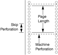
The following SMDR format parameters can be set through system programming in order to match the paper size being used by the printer:
a) Page Length: determines the number of lines per page.
2.18.1 [11-1] MainSMDRlozenge.gifSMDR Format—Page Length (Number of Lines)
[802] SMDR Page Length
b) Skip Perforation: determines the number of lines to be skipped at the end of every page.
2.18.1 [11-1] MainSMDRlozenge.gifSMDR Format—Blank Footer Length (Number of Lines)
[803] SMDR Skip Perforation
The page length should be at least four lines longer than the skip perforation length.

Explanation:

imf1391a.gif
SMDR data is not deleted even if the PBX is reset.
If the PBX is reset during a conversation, the call will not be logged by SMDR.
The following calls are regarded as two separated calls in the SMDR:
Calls before and after the flash/recall/EFA signal is manually sent during a conversation
CO-to-CO line calls by Call Transfer, FWD or DISA (each is logged as both an "incoming call" and an "outgoing call")
The PBX waits for a preprogrammed time period after the end of dialing before starting the SMDR timer for outgoing CO line calls. When the PBX has sent out all dialed digits to the telephone company and this timer expires, the PBX begins measuring the duration of the call. A display proprietary telephone (PT) shows the elapsed time of the call. The starting time and the total duration of the call are logged by SMDR.
2.9.5 [2-3] Timers & CountersDial / IRNA / Recall / Tonelozenge.gifDial—Analog CO Call Duration Start
[208] Call Duration Count Starting Time for LCOT
Serial Interface (RS-232C) Parameters
The following communication parameters can be assigned for the Serial Interface (RS-232C port).
a) New Line Code: Select the code appropriate for the PC or printer. If the PC or printer automatically feeds lines with carriage return, select "CR". If not, select "CR+LF".
2.18.1 [11-1] MainRS-232Clozenge.gifCommunication—NL Code
[800] RS-232C Parameter—New Line Code
b) Baud Rate: Baud rate indicates the transmission speed of data from the PBX to the PC or printer.
2.18.1 [11-1] MainRS-232Clozenge.gifCommunication—Baud Rate
[800] RS-232C Parameter—Baud Rate
c) Word Length: Word length indicates how many bits compose each character.
2.18.1 [11-1] MainRS-232Clozenge.gifCommunication—Word Length
[800] RS-232C Parameter—Word Length
d) Parity Bit: Parity bit indicates what type of parity is used to detect errors in the string of bits composing a character. Make an appropriate selection depending on the requirements of the PC or printer.
2.18.1 [11-1] MainRS-232Clozenge.gifCommunication—Parity Bit
[800] RS-232C Parameter—Parity Bit
e) Stop Bit Length: Stop bit indicates the end of a bit string which composes a character. Select an appropriate value depending on the requirements of the PC or printer.
2.18.1 [11-1] MainRS-232Clozenge.gifCommunication—Stop Bit
[800] RS-232C Parameter—Stop Bit Length
If a call is transferred to an ICD group using Automatic Transfer, the condition code "TR" will not be recorded on SMDR (→ 1.3.9 Call Transfer).

[Host PBX Access Code]

The dialed number including the Host PBX Access code will be recorded on SMDR only if the modified number setting is selected in the ARS setting for SMDR.
When a Host PBX Access code is assigned to a trunk group, calls to extensions of the host PBX are not recorded on SMDR.
A Host PBX Access Code can be used to record only long distance calls on SMDR when a CO line port is connected directly to the telephone company (not a host PBX). This is allowed when the long distance code (e.g., "0") is assigned as the Host PBX Access code. All local calls (e.g., calls that do not require a “0” to be dialed first) are treated as extensions of the telephone company and do not get recorded on SMDR, because in this case this PBX recognizes the telephone company as the host PBX. Therefore, only long distance calls are recorded on SMDR.

[Output to a Telnet compatible Terminal Emulator]

In order to activate a connection to a terminal emulator, the IP address of the IPCMPR card, port number, user ID ("SMDR"), and password must be entered.
If a terminal emulator user incorrectly enters the user ID or password 3 times consecutively, an alarm will be sent and connection will not be possible for 10 minutes.
Through system programming, it is possible to assign the PBX port number and password.

Installation Manual References

3.12.1 Connection of Peripherals

Programming References

PC Programming Manual
2.9.5 [2-3] Timers & CountersDial / IRNA / Recall / Tonelozenge.gifDial—Analog CO Call Duration Start
2.9.12 [2-7-1] Class of Service—COS SettingsCO & SMDRlozenge.gifOutgoing CO Call Printout (SMDR)
2.13.2 [6-2] HotelMainlozenge.gifSMDR for External Hotel Application 2—Printing Message 1–8
2.18.1 [11-1] Main
    → SMDR
    → SMDR Options
    → RS-232Clozenge.gifCommunication—Baud Rate
    → RS-232Clozenge.gifCommunication—NL Code
    → RS-232Clozenge.gifCommunication—Word Length
    → RS-232Clozenge.gifCommunication—Parity Bit
    → RS-232Clozenge.gifCommunication—Stop Bit
PT Programming Manual
[800] RS-232C Parameter—New Line Code
[800] RS-232C Parameter—Baud Rate
[800] RS-232C Parameter—Word Length
[800] RS-232C Parameter—Parity Bit
[800] RS-232C Parameter—Stop Bit Length
[802] SMDR Page Length
[803] SMDR Skip Perforation
[804] SMDR Outgoing Call Printing
[805] SMDR Incoming Call Printing

Feature Manual References

1.3.9 Call Transfer
1.3.20 COS (Class of Service)
1.4.6 DID (Direct Inward Dialing)
1.4.8 DISA (Direct Inward System Access)
1.8.5 Host PBX Access Code (Access Code to the Telephone Company from a Host PBX)
1.9.3 ICD Group Features—Log-in/Log-out
1.13.15 PRIVATE NETWORK FEATURES
2.1 Capacity of System Resources

1.16.4 SNMP (Simple Network Management Protocol) System Monitor

Description

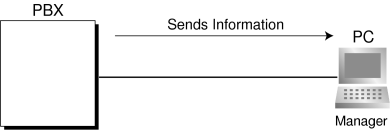
It is possible for a PC assigned as an SNMP manager to manage and receive PBX system status information, such as alarm information and general system activity using SNMP. Management Information Bases (MIBs) are sent to a PC (i.e., the SNMP manager) connected to the PBX over a LAN and can then be stored and analyzed using SNMP manager software.
The two features for managing information using SNMP are as follows:
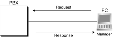
Polling:
A bilateral transaction of information. Polling allows the manager to request information from the PBX.
SNMPpolling.gif
TRAP:
An automatic relay of information from the PBX when a status change occurs or an alarm is detected.
SNMPTRAP.gif

TRAP Implementation

The PBX will send the two types of TRAP as follows:

Type

TRAP Name

Description

Standard TRAP
coldStart
Information is sent after turning on the power of the PBX or resetting the PBX.
Authentication Failure
Information is sent when an unregistered Community Name and/or Manager IP address is entered.
Enterprise Specific TRAP*
Major Alarm
Information is sent when a major alarm is detected.
Minor Alarm
Information is sent when a minor alarm is detected.
*:
Enterprise Specific TRAPs are original TDE exclusive information (Enterprise Specific MIB)

Conditions

Through system programming, it is possible to enable or disable this feature.
Up to 2 SNMP managers can be assigned.
This PBX supports SNMP Protocol Version 1.0 and SNMP Version 1.0-TRAP.
This PBX can only receive read-only MIBs. Write MIBs are not supported.
This PBX supports MIB II.
For more information regarding major and minor alarms, refer to 5.1.5 Troubleshooting by Error Login the Installation Manual.
For a list of the MIB object groups supported by this PBX, refer to 3.3 Supported Management Information Base (MIB) Table in the Appendix.
Through system programming, it is possible to select whether each type of TRAP (e.g., ColdStart) is sent to the SNMP manager or not.

Programming References

PC Programming Manual
2.18.4 [11-4-1] SNMP—System Setting
2.18.5 [11-4-2] SNMP—Manager
PT Programming Manual
None

Feature Manual References

1.10.4 Local Alarm Information

1.16.5 Special Carrier Access Code

Description

If the PBX has access to multiple telephone companies, a Special Carrier Access code assigned through system programming is required every time a CO line call is made without using ARS.
A pause of a preprogrammed length will be automatically inserted between the user-dialed Special Carrier Access code and the subsequent digits. (→ 1.13.4 Pause Insertion)

Conditions

TRS
Toll Restriction (TRS) checks only the dialed telephone number excluding the Special Carrier Access code. (→ 1.17.6 TRS (Toll Restriction))
ARS
A pause is not automatically inserted between the user-dialed access code and the subsequent digits when ARS mode is enabled. (1.1.3 ARS (Automatic Route Selection))
If this PBX is installed behind an existing host PBX:
A Special Carrier Access code and a Host PBX Access code should be assigned separately—these codes cannot be assigned together as one code. (→ 1.8.5 Host PBX Access Code (Access Code to the Telephone Company from a Host PBX))

Programming References

PC Programming Manual
2.14.3 [7-3] Special Carrier
PT Programming Manual
[303] Special Carrier Access Code

Feature Manual References

1.1.3 ARS (Automatic Route Selection)
2.1 Capacity of System Resources

1.16.6 Speed Dialing, Personal

Description

An extension user can make calls using abbreviated dialing for frequently dialed numbers which are stored in the extension's Personal Speed Dialing.
Personal Speed Dialing is also known as Station Speed Dialing.

Conditions

Any number, such as a telephone number or feature number, can be stored in Speed Dialing. A name can be assigned to each Personal Speed Dialing number through personal programming, and also to each System Speed Dialing number.
Call Directory—Speed Dialing
Display proprietary telephone (PT) users can make a call by selecting a stored name shown on the display.
Display Lock
An extension user can lock the Personal Speed Dialing number display to prevent the numbers from being viewed at any extension through personal programming (Display Lock). In this case, the Incoming/Outgoing Call Log displays and the SVM Log display are also locked, and the voice messages in the user's message box cannot be played back. An extension personal identification number (PIN) is required to use this feature. (→ 1.5.6 Extension PIN (Personal Identification Number))

Programming References

PC Programming Manual
2.9.9 [2-6-1] Numbering Plan—MainFeatures
    → lozenge.gifSystem Speed Dialing / Personal Speed Dialing
    → lozenge.gifPersonal Speed Dialing - Programming
2.11.4 [4-1-3] Wired Extension—Speed Dial
PT Programming Manual
None

Feature Manual References

2.1 Capacity of System Resources

Operating Manual References

1.3.61 Speed Dialing, Personal
1.4.1 Call Log, Incoming
1.4.3 Directories
3.1.2 Personal Programming
3.3 System Programming

1.16.7 Speed Dialing, System

Description

An extension user can make calls using abbreviated dialing for frequently dialed numbers which are stored in the PBX as System Speed Dialing numbers.

Conditions

Any number, such as a telephone number or feature number, can be stored in Speed Dialing. A name can be assigned to each Personal Speed Dialing number through personal programming, and also to each System Speed Dialing number.
Call Directory—Speed Dialing
Display proprietary telephone (PT) users can make a call by selecting a stored name shown on the display.
TRS Override by System Speed Dialing
It is possible to override Toll Restriction (TRS) when dialing a number using System Speed Dialing. (→ 1.17.6 TRS (Toll Restriction))
System Speed Dialing Display by AUTO DIAL/STORE Button
Pressing the AUTO DIAL/STORE button on a display DPT or KX-T7735 while on-hook can display the System Speed Dialing Directory.

Programming References

PC Programming Manual
2.9.9 [2-6-1] Numbering Plan—MainFeatureslozenge.gifSystem Speed Dialing / Personal Speed Dialing
2.9.12 [2-7-1] Class of Service—COS SettingsTRSlozenge.gifTRS Level for System Speed Dialing
2.11.4 [4-1-3] Wired Extension—Speed Dial
2.13.1 [6-1] System Speed Dial
2.13.6 [6-6] Tenantlozenge.gifSystem Speed Dial
PT Programming Manual
[001] System Speed Dialing Number
[002] System Speed Dialing Name
[509] TRS Level for System Speed Dialing

Feature Manual References

2.1 Capacity of System Resources

Operating Manual References

1.3.62 Speed Dialing, System
1.4.1 Call Log, Incoming
1.4.3 Directories
3.1.2 Personal Programming
3.3 System Programming

1.16.8 SVM (Simplified Voice Message)

Description

This feature provides simple answering machine features for extensions.
Features for an extension user with a message box:
An extension user can record a personal greeting message to greet a caller and ask him to leave a voice message. The user can also play back and clear greeting messages and the voice messages left by callers.
Feature for a caller:
A caller can leave a voice message after hearing the greeting message.

SVM Block on the IPCMPR Card

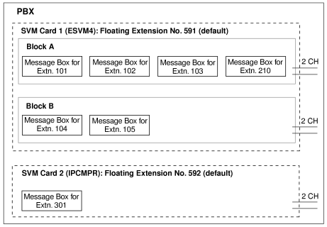
This feature is assigned a floating extension number (default: 591). Two channels are available, allowing two users to access this feature at the same time.
When an extension is assigned to this feature through system programming, a message box is created for that extension. This message box is used to store greeting messages and voice messages for the extension. Each proprietary telephone (PT), single line telephone (SLT), and portable station (PS) can be assigned its own message box.

[Example]

imf2832a.gif

ESVM4 Card

An ESVM4 card, mounted on an OPB3 card, can be used either for the SVM feature, for the OGM feature (→ 1.12.2 OGM (Outgoing Message)), or both.
An ESVM4 card (4 channels) contains two blocks of data. Up to four ESVM4 cards (max. 16 channels) can be installed in the PBX.
Only up to 2 ESVM4 cards (max. 8 channels) can be used for the SVM feature per system. In this case, each card is assigned a floating extension number rather than the SVM block on the IPCMPR card. The rest of the channels must be used for OGM feature purposes.
When using an ESVM4 card for the SVM feature, it must be mounted on sub-slot 3 (highest slot) of the OPB3 card.

[Example]

imf2832aa.gif

Message Recording Limit

Up to 125 (IPCMPR)/250 (ESVM4) messages (greeting messages and voice messages for extensions) with a maximum total recording time of 60 minutes (default) can be recorded per card/block. This memory is shared between the message boxes of all extensions assigned to that card/block. The recording quality, which can be selected through system programming, determines the total recording time as follows:
Recording Quality
Recording Time with the IPCMPR Card
Recording Time with the ESVM4 Card
High
about 40 minutes
about 20 minutes
Middle
(default)
about 60 minutes
about 60 minutes
Low
about 120 minutes
about 120 minutes
When an ESVM card is used for the OGM feature, the recording quality can be set separately (→ 1.12.2 OGM (Outgoing Message)).

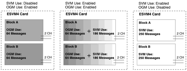
When using an ESVM card for both the SVM feature and OGM feature, the first 64 messages in the card are saved for OGM use and the remaining 186 messages will be for SVM use, as shown below:
imf2832b.gif
If the sum length of all recorded voice messages exceeds 90 % of total recording space, the display informs all extension users that the total capacity has almost been reached. Users will hear dial tone 3 when going off-hook.

Floating Extension No. and Destination

An extension user can set incoming calls to be redirected to his message box when he cannot answer them. The user can set the floating extension number of this feature as the destination for redirected calls. Then, this feature answers redirected calls, plays back the relevant greeting message, and records a voice message. Incoming calls can be redirected to this feature by the following methods:
Call Forwarding (FWD) (→ 1.6.6 FWD (Call Forwarding))
Intercept Routing—No Answer/Busy/DND (→ 1.9.11 Intercept Routing)
[Programming Example for Intercept Routing]

Extension No.

Intercept Destination

Day

Lunch

Break

Night

101
102
591
591
591
102
103
591
591
591
301
(Operator)
591
In this example:
If a call is received at extension 101 and cannot be answered:
a) In day mode: the call will be redirected to extension 102.
b) In lunch/break/night mode: the call will be redirected to this feature, and a voice message will be recorded to the message box.
If a call is received at extension 301 (operator), the call will only be redirected to this feature in night mode.
If both FWD and Intercept Routing features are set for an extension, the FWD setting has priority. So, for example, it is possible for extension 101 to temporarily set FWD settings from his extension to forward calls to the Simplified Voice Message (SVM) feature even during day mode.

Greeting Message for Each Time Mode

When a call is redirected to this feature, the caller hears the designated greeting message. In addition to the normal greeting message, an extension user can record a different greeting message for each time mode (day/lunch/break/night) (→ 1.17.5 Time Service).
[Recording Example]
Normal Greeting Message: "You have reached John. I am sorry I cannot take your call right now. Please leave a message."
Greeting Message for lunch mode: "You have reached John. I am sorry I am out for lunch right now. Please leave a message."
If both the greeting message for a certain time mode and the normal greeting message have been recorded, callers will hear the greeting message for that time mode. However, if no greeting message has been recorded for a certain time mode, the normal greeting message will be played instead.
If neither the normal greeting message nor the greeting message for a certain time mode have been recorded, incoming calls will not be redirected to this feature in that time mode. For example, if a greeting message has only been recorded for night mode, and no normal greeting message has been recorded, incoming calls can only be redirected to this feature in night mode. No incoming calls will be redirected to this feature in day/lunch/break mode.

Direct Recording

An extension user can leave a voice message directly in the message box of an extension. In this case, the target extension will not ring. It is also possible to transfer a caller directly to the message box of an extension.

Message Notification

If a new voice message has been left in a message box, and distinctive dial tones are enabled, the user will hear dial tone 4 when going off-hook. If a message box contains only voice messages that have previously been listened to, dial tone 2 is heard instead. In addition, if the user's telephone has a Message button or Message/Ringer Lamp, the corresponding button or lamp will light when a voice message has been left. Pressing the lit button while on-hook shows the caller's information.

SVM Log

When a caller leaves a voice message on the Simplified Voice Message (SVM) feature, the following information is also recorded (as available):
a. Caller's Name
b. Caller's Telephone Number
c. Time recording started
d. Voice Message Status
"New" is displayed for voice messages which have not previously been listened to.
"Old" is displayed for voice messages which have previously been listened to.
This information can be viewed with the display of a PT or PS.
Please note that the information shown on the display may vary depending on the information that was received and the type of telephone used. Only users of a 6-line display PT can view all of the above information.

Checking Voice Messages Left by Callers

When an extension user accesses his message box, the most recent unplayed voice message is played first. When one voice message finishes playing, the next most recent voice message will begin playing automatically. After the last voice message in a message box has finished playing, the voice messages will begin playing from the most recent voice message again. When all voice messages have been played this time, the extension user will hear dial tone 4, and the line will be disconnected automatically.

SVM Remote Access from CO Line

An extension user can remotely access his message box through a CO line by calling his own extension and using the Walking COS feature. This allows the user to, for example, check the voice messages left in his message box when he is out of the office.

Accessing the Message Box of Another Extension

An extension user can access the message box of another extension by using the Walking COS feature to, for example, record a greeting message in a message box for an Incoming Call Distribution (ICD) Group as described below.
In addition, if the user's telephone has a Message button for another extension, the user can easily access the message box of that extension and listen to the voice messages left by callers.

Message Box for Incoming Call Distribution (ICD) Group

When a call is redirected to this feature from an ICD Group using Intercept Routing—Overflow (→ 1.9.5 ICD Group Features—Overflow) or Call Forwarding (FWD), the greeting message for the first extension assigned to that ICD Group will be played, and the voice message from the caller will be recorded in that extension's message box.
A virtual PS can be assigned as the first extension of the ICD Group. This provides the ICD Group with a dedicated message box that is not shared with an actual extension. (→ 1.19.2 Virtual PS)

Conditions

[General]

Optional Hardware Requirement:
An OPB card, and ESVM4 card
The maximum number of voice messages (not including greeting messages) that can be recorded for an extension can be set between 1 and 100 through system programming. (Default: 10)
The Message button or Message/Ringer Lamp will light when an incoming call is answered by this feature. However, if a message is not left by the caller, the light will turn off when the call has ended.
It is not possible to back up the SVM Log, recorded voice messages or greeting messages. If the PBX is initialized, all this information is cleared.
When the ESVM card to which an extension belongs is changed through system programming, all the recorded voice messages and greeting messages for the extension will be cleared.
When using the IPCMPR card, this feature can be disabled for each extension through system programming. This can be useful for only allowing certain users (e.g., bosses, executives, etc.) access to the limited capacity of recorded voice messages for this feature. When this feature is disabled, all the recorded voice messages and greeting messages for the extension will be cleared.
The voice messages for an extension will be cleared when the extension is checked out using the Hospitality feature (→ 1.8.4 HOSPITALITY FEATURES). However, greeting messages will not be cleared.
An extension is able to receive calls even while a voice message is being recorded in that extension's message box.
If an extension user tries to access this feature when it is already being accessed by two other users, the user will hear a busy tone.
If an extension user tries to clear a voice message shown on the display while the message box is already in use, the extension user will hear a notification tone.
Voice message recording will stop when:
a) a caller hangs up.
b) the recording time for the voice message reaches the preprogrammed limit. (Default: 120 seconds)
c) the recording space reaches the limit.
In cases b) and c), the caller will hear a notification tone, and the line will be disconnected.
New voice messages cannot be recorded in a message box when:
a) the total recording time or number of voice messages exceeds the limit.
b) the number of voice messages for an extension exceeds the limit.
c) the destination of a call has been changed more than once.
d) the desired message box is already in use by another user.
e) a call is received at an ICD Group, and the message box of the first extension assigned to that group is not available, or no extension is assigned as the first member of the group.
This feature does not answer calls that are forwarded using the Call Forwarding by QSIG feature (1.13.22 Private Network Features—QSIG—CF (Call Forwarding)).
Display Lock
A display PT user can lock the SVM Log display to prevent the user's information from being viewed and voice messages from being played back at any extension through personal programming (Display Lock). In this case, the Incoming/Outgoing Call Log displays and the Personal Speed Dialing number display are also locked. An extension personal identification number (PIN) (→ 1.5.6 Extension PIN (Personal Identification Number)) is required to lock/unlock the display.
Accessing the Message Box of Another Extension
Listening to voice messages left by callers using a Message button for another extension is available only when voice messages have been left in the message box.
Moving From SVM to DISA
When a call is answered by SVM but the caller wants to call another extension instead of leaving a message, it is possible to access DISA (DISA OGM 01 will be played) by dialing the Operator Call feature number. This allows the caller to call another extension via DISA or access the DISA AA service.
The OGM feature for the ESVM card to which the SVM mailbox belongs must be enabled via system programming.

[Recording Greeting Messages]

If an extension user tries to record a new greeting message to his message box when the total recording time or number of messages has reached its limit, the user will hear a reorder tone.
It is not recommended to record music when creating a greeting message.

[SVM Remote Access from CO Line]

Whether Walking COS is available or not can be set through system programming.
If the PBX uses analog CO lines without the CPC service, it is strongly recommended to prohibit Walking COS access. If an extension user who is accessing his message box through an analog line goes on-hook while the voice messages are being played, the line will remain connected until all voice messages finish playing. This is because a reorder tone cannot be detected from an analog line while playing voice messages.
The first digit of the Walking COS feature number must be entered before the greeting message finishes playing.
When accessing SVM through a CO line, it is possible to change message boxes (e.g., to leave a message in another user's message box after listening to one's own messages). However, a user can only access the message boxes of other extensions assigned to the same ESVM card. For example, if the user accesses a message box belonging to ESVM card 1 first, then the user can only access the message boxes of other extensions belonging to ESVM card 1. If the user tries to access the message box of another extension belonging to a different card, the user will hear a reorder tone.
While a reorder tone is heard, it is possible to retry another call by pressing "asterisk.gif".

Installation Manual References

3.7.6 ESVM4 Card (KX-TDA0194)

Programming References

PC Programming Manual
2.5.4 Tool—Simplified Voice Message—Delete All Recording
2.5.5 Tool—Simplified Voice Message—Check Current Usage
2.8.5 [1-1] Slot—Card Property - OPB3
2.8.41 [1-1] Slot—OPB3 Card Propertylozenge.gifSVM Feature
2.9.5 [2-3] Timers & CountersMiscellaneous
    → lozenge.gifSVM—Recording Time
    → lozenge.gifSVM—Dial Tone Continuous Time
2.9.9 [2-6-1] Numbering Plan—MainFeatureslozenge.gifSimplified Voice Message Access
2.10.1 [3-1-1] Trunk Group—TRG SettingsTone Detection
    → lozenge.gifSimplified Voice Message Tone Detection—Silence
    → lozenge.gifSimplified Voice Message Tone Detection—Continuous
    → lozenge.gifSimplified Voice Message Tone Detection—Cyclic
2.11.1 [4-1-1] Wired Extension—Extension SettingsOption 6lozenge.gifDisplay Lock / SVM Lock
2.11.9 [4-1-7] Wired Extension—Simplified Voice Message
2.11.10 [4-2-1] Portable Station—Extension SettingsOption 6lozenge.gifSVM Lock
2.11.16 [4-2-5] Portable Station—Simplified Voice Message
2.12.5 [5-3-3] Voice Message—SVM
PT Programming Manual
None

Feature Manual References

1.4.4 Dial Tone
1.12.2 OGM (Outgoing Message)
1.20.1 Walking COS
2.1 Capacity of System Resources

Operating Manual References

1.3.63 SVM (Simplified Voice Message)
3.1.2 Personal Programming

1.16.9 Syslog Record Management

Description

By connecting this PBX to a Syslog server over a LAN, it is possible to output local alarm information (major alarms/minor alarms) to a external PC.

Conditions

To be able to use this feature, through system programming, it is required to enable this feature, register the IP address of the Syslog server, and to select whether major/minor are sent.

Programming References

PC Programming Manual
2.18.1 [11-1] MainSyslog

Feature Manual References

1.10.4 Local Alarm Information